RP-700User’s Manual
3 Appearance and components
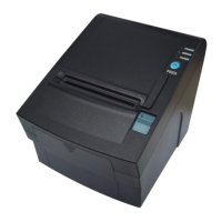
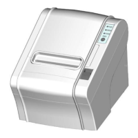
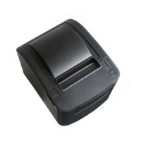
3.1 Appearance and modules
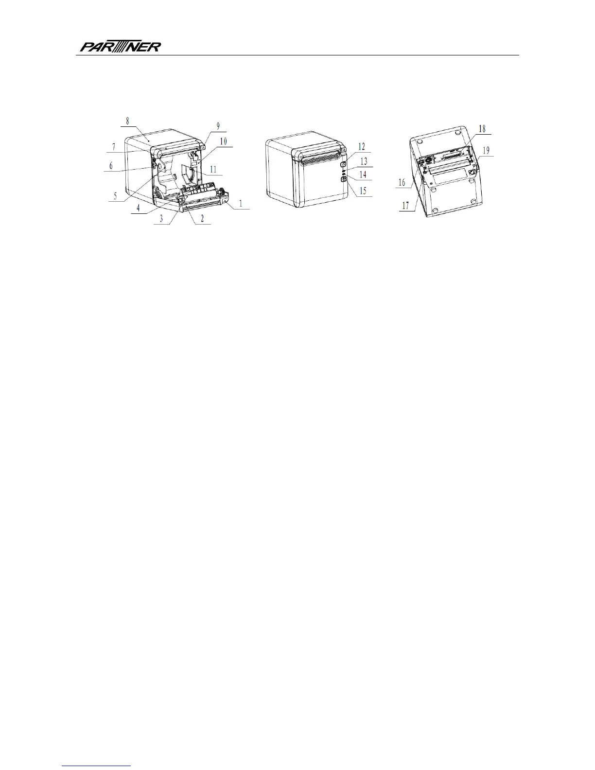
Fig. 3.1-1 Schematic drawing of appearance and modules
1—To p cover 2—Cutter 3—Platen roller
4—Paper end sensor 5—Paper guide 6—Micro switch
7—Cutter cover 8—Middle cover 9—Cover open spanner
10—Paper cabinet 11—Paper near end sensor 12—FEED button
13—ERROR LED 14—POWER LED 15—POWER button
16—USB 17—Power interface 18—Communication interface
19—Cash drawer interface
Button and component function:
a FEED button (12)
Feed paper:
Printer will feed paper when the feed button is pressed down under normal condition. To
feed paper continuously, keep pressing the button.
Print configuration sample:
Pressing down the feed button while turning on the power, the printer will print out the
configuration sample, which includes print width, print speed, etc.
Enter button configuration mode:
Press down the feed button while turning on the power, the printer will print out the
configuration sample, andenter pause status (error LED flashes) after cutting paper. Keep
pressing the feed button at this time, the printer will enter button configuration mode.
Press the button to clear the cutter error:
Press the button for a short time when a cutter error occurs, the printer will try to clear the
cutter error automatically.
b Error LED (13)
Indicate printer status. Under normal status, the error LED is off. Under error status (e.g.
paper end, etc.), the error LED flashes.
c Power LED (14)
Indicate printer power status (ON/OFF).
d Power button (15)
- 5 -