XTM WF100
4T
2T
10
8
9
2
1
4
PUSH PULL
CONTROL 4 2 V
16
17
18
19
20
21
7
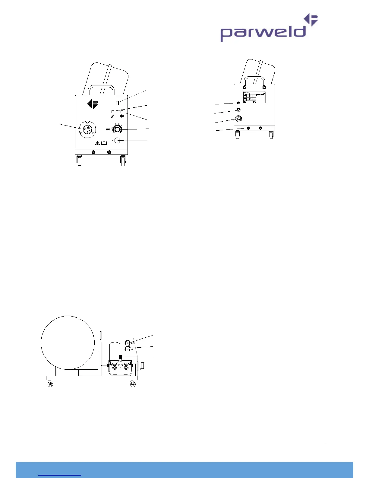
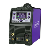
4.0 Descripon of controls
1. Digital display for amperage and Voltage
(displayed real me)
2. Fault light This light will illuminate when a fault or
over temperature condion has occurred. If this
light illuminates allow the machine to cool with
the fan sll running unl it exnguished. If the
light does not go o when the power source has
cooled down then have the machine checked by a
qualied engineer.
3. Mains input light This light illuminates when the
mains power is connected and the machine is
switched on.
4. On O switch. The machine is switched o when
the light (4) is o and the fan is not running.
5. Coarse Voltage selector switch. This switch is used
to select the require welding voltage each posion
of the switch represents approximately 4V.
Do Not operate this switch while welding
6. Fine Voltage selector switch. This switch is used to
select the require welding voltage each posion of
the switch represents approximately 0.5V.
Do Not operate this switch while welding
7. Work return lead connecon. This socket allows
connecon of the work return lead to the front of
the machine.
Note the XTM403S has 2 sockets for the work return
lead please refer below
8. Work return lead connecon. High inductance
connecon, this should be used when in spray
transfer mode to give a more stable arc. (Only
ed to XTM403S)
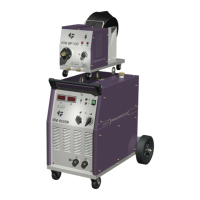
9. Mains input connecon Input connecon for the
pre-installed mains cable
10. Control circuit protecon fuse.
11. Gas cylinder retenon chain to be used when a
gas cylinder is mounted on the rear tray.
12. Auxiliary output. 240V 3A auxiliary output for use
with water cooler or small power tools.
13. Protecon fuse for the Auxiliary output
14. Socket for the interconnecon cable to link to the
wire feeder.
15. Welding power connecon to connect to the inter
connect cable.
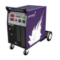
16. 2T 4T, when in the 2T posion the torch trigger
will have a momentary operaon ie the welding
operaon will start when the rigger is depressed
and stop when it is released. In the 4T posion a
short press and release of the trigger will start the
welding operaon and a short press and release
with stop the operaon. The 4T mode is ideal for
long welds as it reduces operator fague.
17. Gas purge buon. Pressing this buon allow gas
to ow through the welding torch and so allow
checking of the gas ow before starng the
welding process.
18. Wire inching buon, allows the welding wire to
be fed through the torch without engergising the
welding power.
19. Wire feed speed adjustment, controls the speed of
wire feeding from 0.8 to 24 m/min. Increasing the
wire feed speed also has the eect of increasing
the welding current
20. Locaon for control socket if machine is ed with
Push Pull torch
21. Torch connector The Euro connector provided the
external connecon for the welding torch
9
4
3
9
4
3
22
23
24
60A/17V to 350A/31.5V
X 60% 100%
1 ~50 Hz
U1 = 42V
IP 21 S
Rohs Compliant
ENGLAND.
DY12 2TZ,
WORCESTERSHIRE,
LONG BANK BEWDLEY,
BEWDLEY BUSINESS PARK,
PARWELD LTD,
S No.
ISO/IEC 60974-1
I2 500A 350A
M
I1 eff = A
WIRE FEEDER
CON TRO L
INTERCONNECTING
CAB LE
GAS I NPUT
25
26
27
27