it securely into the top of the machine. Li the wire
feeder up onto the power source and locate the post
into the tube on the underside of the wire feeder
taking care to ensure it is fully located on the post.
Connecon of the interconnect cable.
Working at the wire feeder end insert the Dinse power
connector and twist it to lock it securely. Connect the
gas hose to the inlet on the rear of the wire feeder
followed by the 4 pin plug taking care to align the pins
before inserng the plug.
At the power source end connect the Dinse socket and
twist to secure, connect the 5 pin control socket taking
care to align the pins before inserng the plug. The
gas hose should be lead o to the outlet connecon of
the gas regulator.
5.5 Output Polarity Connecons
The welder, as shipped from the factory, is connected
for electrode posive (+) polarity. This is the normal
polarity for MIG welding.
5.6 Changing drive roll sets
NOTE: Be sure that the torch liner and contact p are
also sized to match the selected wire size.
5.7 Welding wire installaon
1. Open the Wire drum cover by pulling down and
out on the boom of the cover
2. Unscrew the plasc retaining wheel from the end
of the spool holder sha.
3. Posion the wire spool so that it will rotate in a
direcon when feeding so as to be de-reeled from
the boom of the coil.
4. Slide the wire spool all the way onto the sha and
ret the plasc retaining nut.
Note:- There is a fricon brake on the reel hub
assembly to prevent the wire spool over running
when welding stops ensure the this is slackened to the
minimum seng. It can be adjusted by means of the
nut visible when the plasc nut is removed.
5. Turn the Spool unl the free end of the electrode
is accessible. While securely holding the
electrode, cut o the bent end and straighten the
rst six inches. (If the electrode is not properly
straightened, it may not feed properly through the
wire drive system Manually feed the wire from
the wire reel and through the wire guide and then
over the top of the wire feed rollers (ensure the
pressure arms are in the raised posion.)
6. Connue to feed the wire through the outlet
guide unl 20mm of wire is protruding from the
front of the machine torch connector.
7. Reposion the adjustable pressure arms to
there original posion to apply pressure. Adjust
pressure as necessary.
Note the pressure arm should be adjusted in order to
give the minimum amount of pressure on the wire to
allow reliable feeding,
5.8 torch installaon
Your Parweld MIG/MAG Welding Torch has been
supplied ready to weld. It has been supplied with
the standard consumables denoted in the product
brochure.
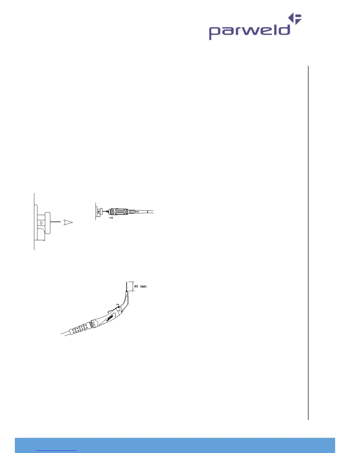
To connect the torch to the power source:-
1. Remove the p adaptor and contact p
2. Inch the wire from the exit of the wire guide on
the feed unit as Figure 1. Ensure that it does not
short out on any machine panels.
3. Carefully slide the electrode wire into the torch
liner and slowly locate the torch gun plug body
into the feed unit central connector and ghten
the gun plug nut as Figure 2
Note; To aid the inial locaon of a new torch and to
prevent damage to the gas nipple O-ring a very light
applicaon of grease to the O Ring is benecial.
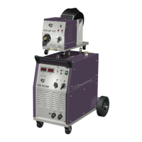
4. Keeping the torch as straight as possible, use the
power source inch facility or torch trigger to feed
the electrode wire 50mm from the end of the liner
conduit.
5. Once the electrode wire has stopped, ret the p
adaptor, diuser, contact p and gas nozzle.