SERIES 3300
9
2.7 USCITE DI POTENZA
Le uscite di potenza per i diffusori sono disponibili sulla morsettiera [20].
È possibile realizzare un impianto di diffusione sonora utilizzando sia
diffusori a bassa impedenza, sia diffusori dotati di traslatore di linea.
In entrambi i casi il carico complessivo non deve essere tale da
sovraccaricare l’amplificatore: non applicare cioè diffusori o gruppi di
diffusori con impedenza più bassa di quella nominale della presa alla
quale sono collegati. Si raccomanda inoltre di porre particolare attenzione
al calcolo delle impedenze nel caso si debbano realizzare impianti di
diffusione misti (a bassa impedenza e a tensione costante).
In tabella 2.7.1 sono riportati i valori nominali di tensione ed impedenza
per le diverse uscite.
Tabella/Table 2.7.1
Fig. 2.7.1
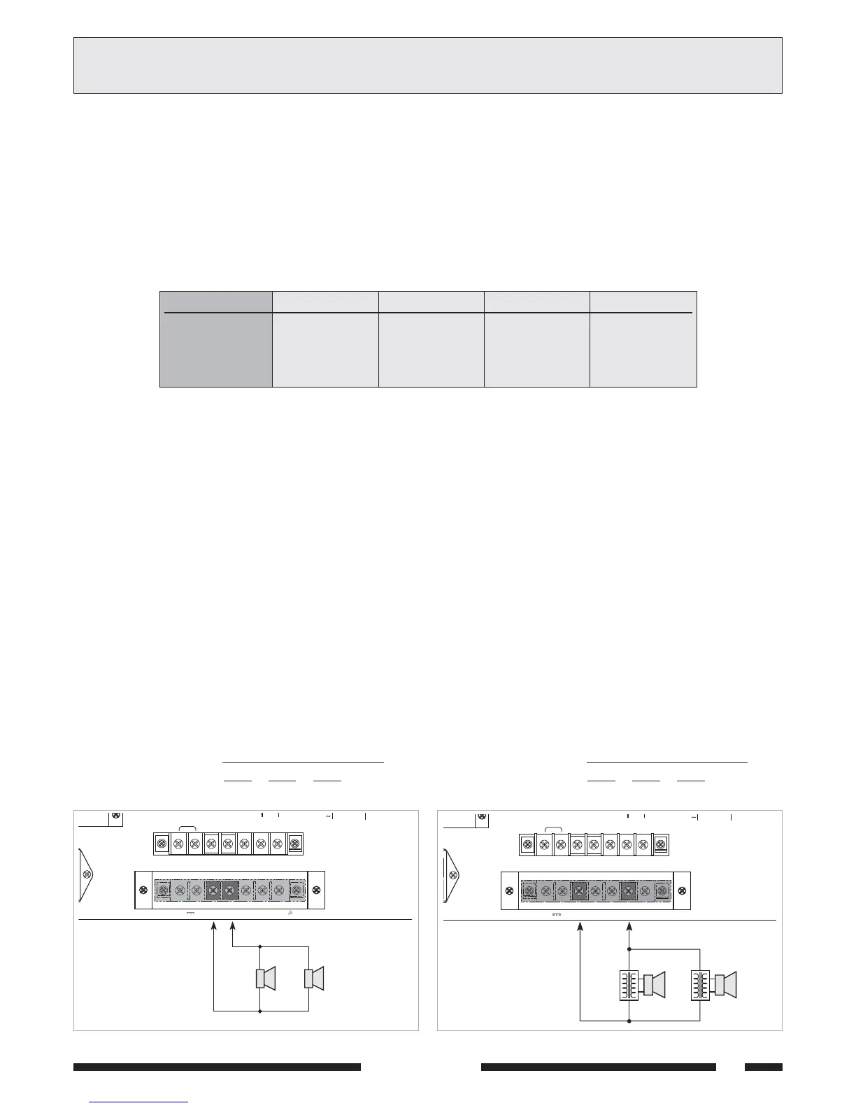
2.7.1 Sistemi a bassa impedenza
In applicazioni che richiedono l’uso di pochi altoparlanti, la linea di
collegamento può essere connessa tra il terminale comune COM e la
presa 8
ΩΩ
ΩΩ
Ω della morsettiera [20]. Il collegamento degli altoparlanti, di
tipo serie, parallelo o misto, deve fornire un’impedenza calcolata pari o
superiore a quella nominale della presa considerata.
In figura 2.7.1 é riportato un esempio di collegamento.
CONNECTIONS
2CONNESSIONI
Fig. 2.7.2
1W/8
W
HOT COM GND
120W RMS 300W
230/115V
PREC.
+
P
100V70V50V
8
W
COM.24V 4A
+–
20W20W
2.7 POWER OUTPUTS
The power outputs for the loudspeakers are available on the terminal
strip [20]. It is possible to set up a sound-broadcasting system
using either low-impedance loudspeakers or loudspeakers equipped with
a line transformer. In both cases the overall load must not be such as to
overload the amplifier. This means that you must not apply loudspeakers
or groups of loudspeakers with an impedance lower than the rated
impedance of the socket to which they are connected. It is also
necessary to pay particular attention to calculating the impedance values
if mixed broadcasting systems (low impedance and constant voltage)
are to be set up. Table 2.7.1 shows voltage and impedance rated values
for the various outputs.
2.7.1 Low-impedance systems
In applications that require the use if a small number of loudspeakers, the
connecting line can be connected between the common terminal COM
and the 8
ΩΩ
ΩΩ
Ω socket of the terminal strip [20]. The connection of the
loudspeakers, whether of the serial type or parallel type or mixed, must
provide an impedance calculated to be equal to or higher than the rated
impedance of the socket considered. An example of a connection is shown
in Fig. 2.7.1.
• Calcolo dell’impedenza nei collegamenti in serie
Nel caso di diffusori collegati in serie tra loro, l’impedenza totale è la
somma delle singole impedenze:
impedenza totale = Z1 + Z2 + Z3 + ....
• Calcolo dell’impedenza nei collegamenti in parallelo
Nel caso di diffusori collegati in parallelo tra loro, l’impedenza totale può
essere determinata mediante la seguente formula:
1
1
Z1
1
Z2
+
1
Z3
+ + ......
impedenza totale =
• Calculating the impedance value in series connections
In the case of loudspeakers connected to one another in series, the total
impedance is the sum of the single impedance values:
Total impedance = Z1 + Z2 + Z3 + ....
• Calculating the impedance value in parallel connections
In the event of loudspeakers connected in parallel to one another the
total impedance can be calculated by means of the following formula:
1
1
Z1
1
Z2
+
1
Z3
+ + ......
Total impedance =
AX3304
17,9 V
62,5 Ω
122,5 Ω
250 Ω
AX3306
22 V
42 Ω
82 Ω
167 Ω
AX3312
31 V
20,8 Ω
40,8 Ω
83,3 Ω
Uscita - Output
8 Ω
50 V
70 V
100 V
AX3303
15,5 V
83,3 Ω
163,3 Ω
333,3 Ω