Page 74
77-78 38 Input 1 mode —Logic See correspondence on page 43
79-80 39 Input 1 mode —Polarity See correspondence on page 44
81-82 40 Input 1 mode —Stability See correspondence on page 44
83-84 41 Hysteresis input 1 INT. value
85-86 42 Timing input 1 INT. value
87-88 43 Delay input 1 INT. value
89-90 44 Input 2 mode —Function See correspondence on page 44
91-92 45 Input 2 mode —Logic See correspondence on page 45
93-94 46 Input 2 mode —Polarity See correspondence on page 45
95-96 47 Input 2 mode —Stability See correspondence on page 45
97-98 48 Hysteresis input 2 INT. value
99-100 49 Timing input 2 INT. value
101-102 50 Delay input 2 INT. value
103-104 51 Analogue Fixed Tare (MSB) INT. value - Most significant word
105-106 52 Analogue Fixed Tare (LSB) INT. value - Less significant word
107-108 53 Analogue Full Scale (MSB) INT. value - Most significant word
109-110 54 Analogue Full Scale (LSB) INT. value - Less significant word
111-112 55 Analogue Output Mode See correspondence on page 35
113-114 56 Analogue Output Range See correspondence on page 35
(*) These registers can only be modified in FREE mode or if in METRIC mode with a calibration
bridge enabled.
WRITING EXAMPLES
To write the set-up parameters following the example:
In the bytes 1-2 (Command Register) write value Hex 3FFF. This value opens the writing area of the
DAT 1400.
Example: to change the default values of the DAT 1400 like the Capacity of the load cells, the Sensitivity
and Division value to 15000, 2.9965 and 2:
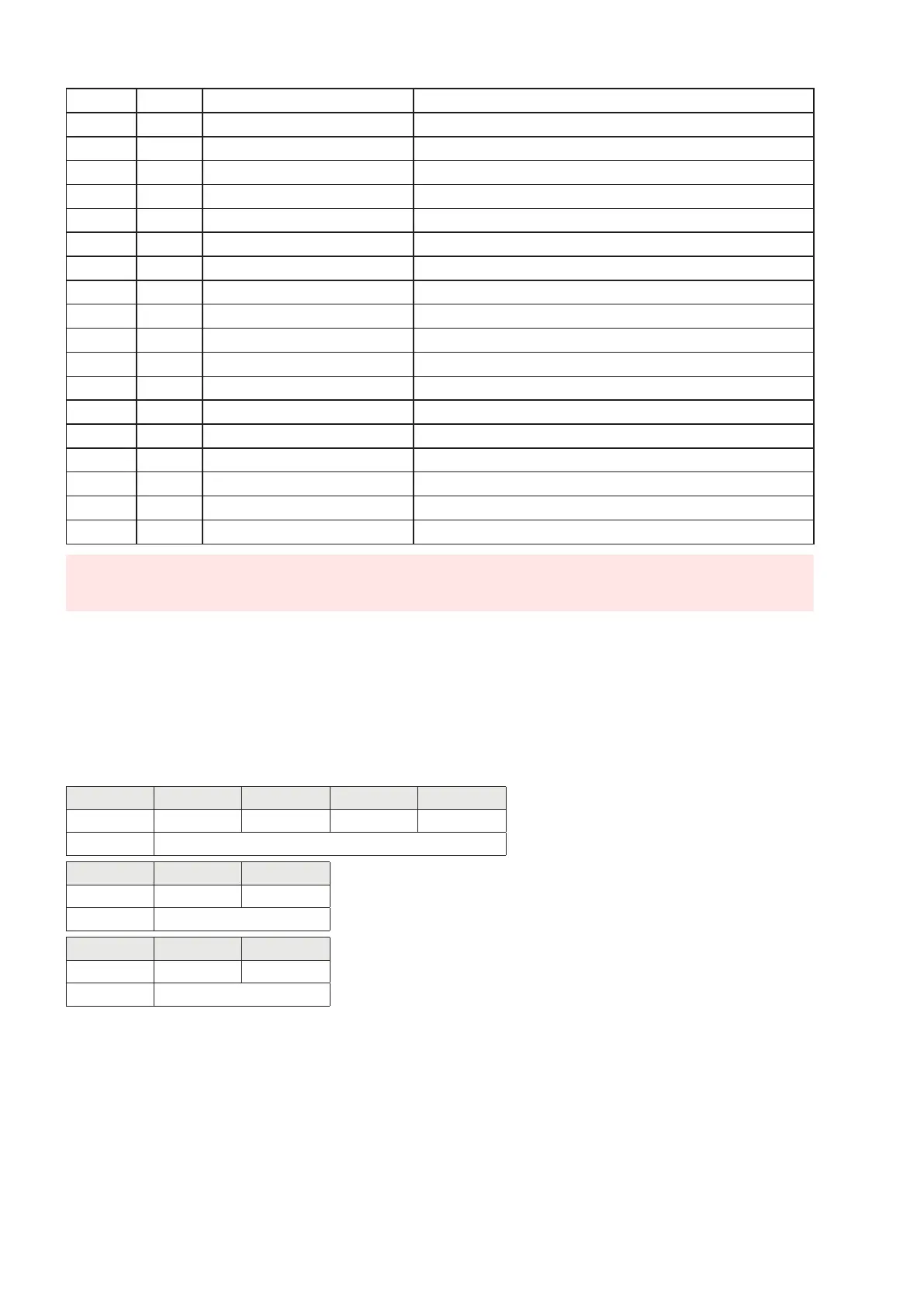
Capacity Byte 17 Byte 18 Byte 19 Byte 20
Hex 00 00 3A 98
Dec 15000
Sensitivity Byte 21 Byte 22
Hex 75 0D
Dec 29965
Division Byte 23 Byte 24
Hex 00 0D
Dec 13
Save the data by writing the value Hex 7 in Command Register.
N.B. The DAT 1400 does not accept writing of the same values already written.
To perform Zero and FS Calibration it is not needed to abilitate the internal Writing Area of the DAT
1400.
Zero Calibration:
Whit empty system put Hex 4 in Command Register (bytes 1-2). The new Zero value is stored.