31
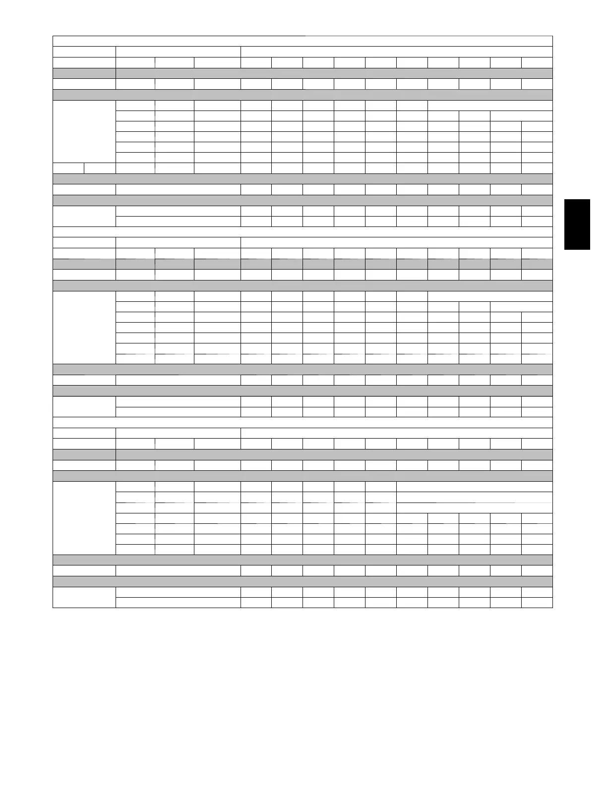
Table 9 -- Cooling
4
and Heating Air Delivery -- CFM (Bottom Return
5
with Filter) (Continued)
(SW1-5 a nd SW2---2 set to OFF, except as indicated. See notes 1 a nd 2.)
Unit Size Cooling Switch Settings External Static Pressure (ESP) In. W.C.
SW2-8 SW2-7 SW2-6 0.1 0.2 0.3 0.4 0.5 0.6 0.7 0.8 0.9 1.0
60080
Clg Default: OFF OFF OFF 1905 1870 1825 1785 1750 1700 1665 1625 1560 1460
Cooling (SW2)
OFF OFF ON 950 770 620 515 440 365 Seenote4
OFF ON OFF 1015 935 880 825 765 690 625 580 Seenote4
OFF ON ON 1155 1105 1040 990 920 875 815 755 710 645
ON OFF OFF 1335 1290 1245 1190 1145 1085 1040 990 930 890
ON OFF ON 1520 1485 1435 1390 1340 1300 1255 1200 1160 1115
ON ON OFF 1905 1870 1825 1785 1750 1700 1665 1625 1560 1460
ON ON ON 2290 2230 2160 2085 2005 1915 1820 1730 1640 1525
Clg SW2: Maximum Clg Airflow
2
2290 2230 2160 2085 2005 1915 1820 1730 1640 1525
Heating
(SW1)
High Heat Airflow
3
1575 1535 1485 1445 1400 1350 1310 1260 1215 1170
Low Heat Airflow
3
1230 1170 1125 1065 1015 955 900 855 795 755
Unit Size Cooling Switch Settings External Static Pressure (ESP) In. W.C.
SW2-8 SW2-7 SW2-6 0.1 0.2 0.3 0.4 0.5 0.6 0.7 0.8 0.9 1.0
60100
Clg Default: OFF OFF OFF 1890 1845 1800 1755 1700 1655 1610 1560 1510 1460
Cooling (SW2)
OFF OFF ON 1015 825 630 485 405 325 Seenote4
OFF ON OFF 1080 895 815 740 690 615 555 475 Seenote4
OFF ON ON 1155 1080 1020 940 890 825 785 710 660 590
ON OFF OFF 1310 1260 1195 1140 1075 1025 970 925 875 810
ON OFF ON 1520 1475 1425 1365 1315 1255 1210 1155 1110 1055
ON ON OFF 1890 1845 1800 1755 1700 1655 1610 1560 1510 1460
ON ON ON 2290 2230 2160 2085 2005 1915 1820 1730 1640 1525
Clg SW2: Maximum Clg Airflow
2
2290 2230 2160 2085 2005 1915 1820 1730 1640 1525
Heating
(SW1)
High Heat Airflow
3
1905 1865 1825 1775 1730 1685 1640 1590 1545 1490
Low Heat Airflow
3
1480 1435 1375 1330 1265 1215 1160 1115 1060 1005
Unit Size Cooling Switch Settings External Static Pressure (ESP) In. W.C.
SW2-8 SW2-7 SW2-6 0.1 0.2 0.3 0.4 0.5 0.6 0.7 0.8 0.9 1.0
66120
Clg Default: OFF OFF OFF 2010 1960 1910 1850 1800 1750 1690 1645 1565 1480
Cooling (SW2)
OFF OFF ON 1015 805 645 550 480 Seenote4
OFF ON OFF 1075 975 915 835 765 Seenote4
OFF ON ON 1205 1135 1055 1000 935 Seenote4
ON OFF OFF 1400 1330 1260 1190 1145 1080 1035 970 905 845
ON OFF ON 1615 1550 1500 1435 1370 1325 1265 1215 1160 1110
ON ON OFF 2010 1960 1910 1850 1800 1750 1690 1645 1565 1480
ON ON ON note 8 2375 2300 2205 2115 2010 1890 1750 1645 1550
Clg SW2: Maximum Clg Airflow
2
note 8 2375 2300 2205 2115 2010 1890 1750 1645 1550
Heating
(SW1)
High Heat Airflow
3
note 8 2375 2300 2205 2115 2010 1890 1750 1645 1550
Low Heat Airflow
3
1735 1675 1625 1560 1500 1455 1395 1345 1285 1225
1. Nominal 350 CFM/ton cooling airflow is delivered with SW1-5 and SW2 ---2 set to OFF.
Set both SW1-5 and SW2---2 to ON for +7% airflow (nominal 370 CFM/ton).
Set SW1-5 to ON and SW2---2 to OFF for +15% airfl o w (nominal 400 CFM/ton).
Set SW2--- 2 to ON and SW1-5 to OFF for -7% airflow (nominal 325 CFM/ton).
The above adjustments in airflow are subject to motor horsepower range/capacity .
2. Maximum cooling airflow is achieved when switches SW2-6, SW2-7, SW2-8 and SW1-5 are set to ON, and SW2---2 is set to OFF.
3. All heating CFM's are when low heat rise adjustment switch (SW1-3) and comfort/efficiency adjustment switch (SW1-4) are both set to OFF.
4. Ductwork must be sized for high-heating CFM within the operational range of E.S.P . Operation within the blank areas of the chart is not recommended
because high-heat operation will be above 1.0 E.S.P.
5. All airflows of 1800 CFM or less o n 21” and 24.5” casing size furn a ces are 5% less on side return only installations.
6. Return air above 1800 CFM on 24.5” casing requires two sides, one side and bottom, or bottom only to all ow sufficient airflow to the furnace.
7. For upflow applications, air entering from one side into both the side of the furnace and a return air base counts as a side and bottom return.
8. Airflow not stable at this E.S.P.
PG96VAT
 Loading...