12
CONDENSATE TRAP
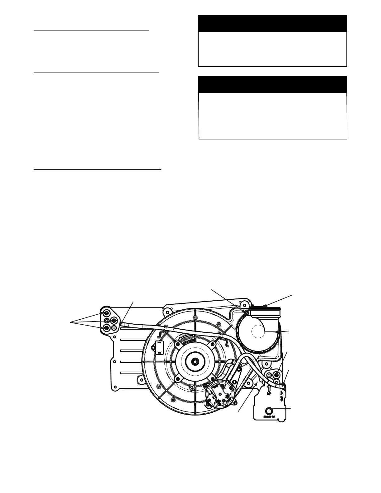
Condensate Trap -- Upflow Orientation
When the furnace is installed in the upflow position, it is not
necessary to relocate the condensate trap or associated tubing.
Refer to Fig. 8 for upflow condensate trap information. Refer to
Condensate Drain section for information how to install the
condensate drain.
Condensate Trap -- Downflow Orientation.
When the furnace is installed in the downflow position, the
condensate trap will be initially located at the upper left corner of
the collector box, as received from the factory. See the top image
in Fig. 9. When the furnace is installed in the downflow
orientation, the condensate trap must be relocated for proper
condensate drainage. See the bottom image in Fig. 9.
To Reloca te the Condensate Trap:
S Ori ent the furnac e in the downflow position.
S Fig. 9 shows the condensa te tr ap and tubing before and after
relocation. Re fer to Fig. 9 to begin the tr ap conversion.
S Refer to Condens ate Dra in section for inf or m ation how to ins tall the
condensa te drain.
Condensate Trap -- Horizontal Orientation.
Whe n t he fur nace is instal l ed in the horizont al ri ght position, the
condensa te tr ap will be i nitially located at the bottom of the collector
box, as received from the factory. See the top image in Fig. 10.
When the furnace is installed in the horizontal left position, the
condensa te trap will be initially located at the top of the collector box,
as received from the factory . See the top image in Fig. 11. In both
case s the trap must be repositioned on the col lec t or box for proper
condensa t e dra inage. See the bottom images in Fig. 10 and 11.
A field--supplied, accessory Horizontal Installation Kit (trap
grom met) is re qui red for al l dir ect--vent hori zonta l instal l ations (onl y).
The kit contains a rubber casing gromme t des i gned to seal between
the furnace casi ng and the conde nsate tr ap. Se e Fig. 17.
The field--supplied, accessory horizontal drain trap grommet is
ONLY REQUIRED FOR DIRECT VENT APPLICATIONS.
It it NOT required for applications using single--pipe or
ventilated combustion air venting.
NOTICE
The condensate trap extends below the side of the casing in
the horizontal position. A minimum of 2 --in. (51 mm) of
clearance is required between the casing side and the furnace
platform for the trap to extend out of the casing in the
horizontal position. Allow at least 1/4-- in. per foot (20 mm
per meter) of slope down.
NOTICE
To Reloca te the Condensate Trap:
S Remove the knoc kout in the ca sing for the condensat e trap.
S Instal l the gromme t in the casing when re qui red for direct--vent
horizontal applicati ons .
S Orient the furnace in the desired position.
S All ow for 2 in. (51 mm) of cl ear ance under neat h the fur nace for the
condensa te tr ap and drain li ne.
S Fig. 10 shows the condensa te tr ap and tubing before and after
relocati on in the horizontal right position.
S Fig. 11 shows the condensa t e trap and tubi ng bef or e and after
relocati on in the horizontal left posi tion.
S Refer to the appr opriate figure to begin the trap conversion.
S Refer to Condens ate Dra in section for inf or m ation how to ins tall the
condensa te drain.
Condensate Trap
Relief Port
Collector Box
Plugs
Pressure Switch
Port
Condensate Trap
Outlet
Condensate Trap
Relief Port
Collector Box
Plug
Vent Elbow
Vent Elbow Clamp
Vent Pipe Clamp
UPFLOW TRAP CONFIGURATION
1 & 2 Stage Units
A11307
Fig. 8 -- Upflow Trap Configuration
(Appearance may vary)