8
PG9YAA036060
21
5
/
8
1
3
/
8
8
11
/
16
TOP
F
G
E
H
AIR INTAKE
VENT
ELECTRICAL
1
1
/
4
TRAP (KO) (COUNTERFLOW)
LEFT SIDE
GAS
VENT
4
13
/
16
1
1
/
16
AIR INTAKE (KO)
(ALTERNATE)
TRAP (KO)
UPFLOW/HORIZONT AL
THERMOSTAT
1
11
/
16
17
5
/
16
24
1
/
16
28
3
/
4
29
7
/
8
31
11
/
16
13
11
/
16
19
13
/
16
2
1
/
4
13
1
/
4
1
7
/
8
21
5
/
8
24
4
7
/
8
7
FRONT
A
B
D
BOTTOM
3
7
/
8
23
1
/
8
2
3
/
8
AIR INTAKE (KO)
(ALTERNATE)
RIGHT SIDE
TRAP (COUNTERFLOW)
ELECTRICAL (KO)
VENT (KO)
TRAP (KO)
UPFLOW/HORIZONT AL
THERMOSTAT
1
1
/
4
2
7
/
8
28
1
/
2
18
1
/
2
3
/
4
TYP.
4
5
/
16
1
1
/
16
GAS
4
13
/
16
1
11
/
16
17
5
/
16
1
11
/
16
27
3
/
16
29
7
/
8
21
5
/
8
33
11
/
16
1
7
/
8
9
13
/
16
1
3
/
16
4
7
/
8
2
1
/
4
24
40
19
1
/
4
7
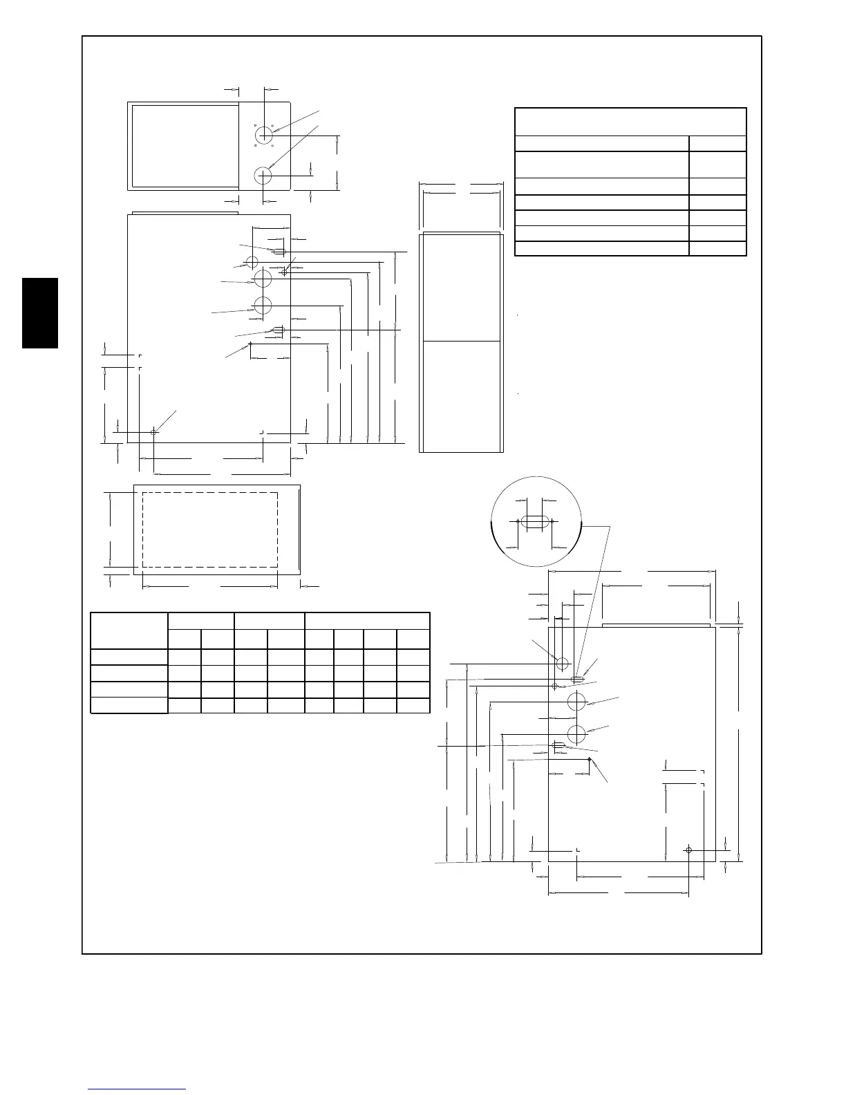
ALL DIMENSIONS IN INCHES
1IN=25.4MM
Drawing is representative,
but some models may vary
NOTE: Evaporator “A” coil drain pan dimensions
may vary from furnace duct opening size. Always
consult evaporator specifications for duct size
requirements.
Furnace is designed for bottom return or side
return.
Return air through back of furnace is NOT allowed.
C
(KO)
KO = Knockout
(KO)
Specifications are subject to change without notice
MINIMUM CLEARANCES TO
COMBUSTIBLE MATERIALS FOR ALL UNITS
REAR 0
FRONT (combustion air openings in
furnace and in structure)
3″
Required For Service
*24″
ALL SIDES Of SUPPLY P LENUM 1″
SIDES 0
VENT 0
TOP OF FURNACE 1″
*30″ clearance recommended for furnace removal.
Horizontal position: Line contact is permissible only between
lines formed by intersections of top and two sides of furnace
jacket, and building joists, studs or framing.
Unit
Ca pacity
Cabinet Bott om Top
ABC DEFGH
19
1
/
8
17
5
/
8
2
1
/
8
14
3
/
4
4
3
/
8
4
1
/
2
2
1
/
2
9
1
/
2
22
3
/
4
21
1
/
4
1
15
/
16
18
3
/
4
4
3
/
8
4
1
/
2
2
5
/
8
11
3
/
8
22
3
/
4
21
1
/
4
1
15
/
16
18
3
/
4
4
3
/
8
4
1
/
2
2
5
/
8
11
3
/
8
PG9YAA048080
24
1
/
2
23
7
/
16
23 4
3
/
8
4
1
/
2
2
1
/
4
12
1
/
4
PG9YAA036080
PG9YAA060100
A07701
Fig. 2 -- Dimensions and Clearances
PG9YAA
 Loading...