9
A07702
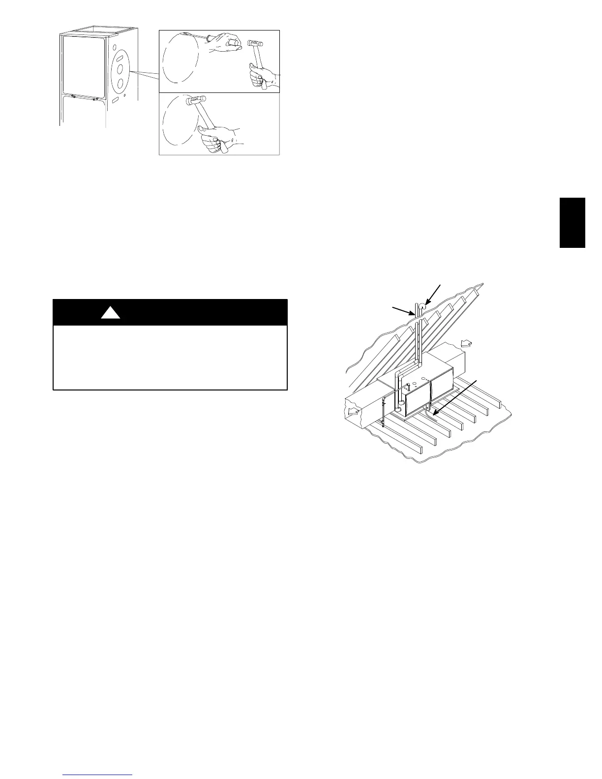
Fig. 3 -- Hammer and Screwdriver used for Knockout
NOTE: If a knockout does not come out after two sharp blows,
pull and snip as needed to remove the knockout.
Installation Positions
This furnace can be installed in an upflow or horizontal (either
left or right) airflow position. DO NOT install this furnace in the
downflow position or on its back. For the upflow position, the
return air ductwork can be attached to either the left or right side
panel and/or the bottom. For horizontal positions, the return air
ductwork must be attached to the bottom:
CARBON MONOXIDE POISONING HAZARD
Failure to follow this warning could result in personal injury or
death.
Do NOT install this furnace in DOWNFLOW applications.
!
WARNING
Furnace Installation Considerations
The installation of the furnace for a given application will dictate
the position of the furnace, the airflow, ductwork connections,
vent and combustion air piping. Consideration must be given to
the following:
Condensate Trap and Drain Lines
The supplied condensate trap must b e attached to the furnace side
panel on either the left or right side. For horizontal installations,
the d rain trap is vertically attached to the side panel below the
furnace. A minimum clearance of 6″ below the furnace is
required for the condensate trap. Downward slope of the
condensate drain line from the condensate trap to the drain
location must be provided. Adequate freeze protection of the
drain trap and the drain line must be provided. See “Condensate
Drain Trap” section for further details.
Leveling
Proper leveling of the furnace must be provided to insure proper
drainage of the condensate from the furnace. The furnace must be
level to within
1
/
4
″ (6.35 mm) fro m front to back and from s ide to
side for upflow installations or top to bottom for horizontal
installations.
Vent and Combustion Air Connections
For venting information literature, contact www.cac--bdp.com
with the complete model and serial number of the furnace.
NOTE: Furnaces installed in Canada must use vent systems that
are certified to the standard for Type BH Gas Venting Systems,
ULC-- S636. ULC--S636 certified plastic vent system material or
the components of ULC--S636 certified vent systems must not be
interchanged with other vent systems or unlisted pipe/fittings.
Vent components supplied with the furnace and components in
factory authorized vent kits may be used with ULC-- S636
certified vent systems.
The ULC--S636 certified plastic components, and specified
primers and glues of the certified system must be from a single
system manufacturer and not intermixed with other system
manufacturer’s vent system parts.
The first 3 ft. (900 mm) of the venting system must b e readily
accessible for inspection.
In some provinces the combustion air system may also be
required to be ULC--S636 certified.
The vent and combustion air pipes attach to the furnace through
the top panel or to the alternate locations on the furnace side
panels.
Note: Repositioning of the combustion blower is required for the
vent pipe connection to the furnace through the “right side”
panel. See “Vent and Combustion Air Piping” section for furth er
details.
Horizontal Furnace Installation
Inlet Pipe (not used on Single Pipe model)
Vent
Pipe
Condensate
Trap
NOTE: 6
bottom clearance required for condensate trap.
A07703
Fig. 4 -- Typical Horizontal Installation
This furnace can be installed horizontally in an attic, basement,
crawl space, alcove, or suspended from a ceiling in a basement or
utility room. See Fig. 4.Donotinstall furnace on its back or in
the reverse airflow positions as safety control operation will be
adversely affected.
If the furnace is to be installed in a crawl space, consult local
codes. A suitable concrete pad or blocks are recommended for
crawl space installation on the ground.
NOTE: 6″ bottom clearance required for condensate trap.
Twenty four (24) inches between the front of the furnace and
adjacent construction or other appliances MUST be maintained
for service clearance.
Keep all insulating materials clear from louvered door. Insulating
materials may be combustible.
The horizontal furnaces may be installed directly on combustible
wood flooring or supports as long as all required furnace
clearances are met. See Fig. 4.
PG9YAA
 Loading...