Page 17
Ph: 804.227.3023
10511 Old Ridge Rd. Ashland, VA 23005
4LHD/4LHDX Application Manual
Powertrain Control Solutions
REV 1.1
1.5.2 Internal Wiring
Unless otherwise specied, electrical components operating range shall be 8.0 to 18.0 VDC. It is recommended that
the transmission controls solenoids are not engaged without the engine running. Transmission electrical components
should be fused separately from other vehicle components.
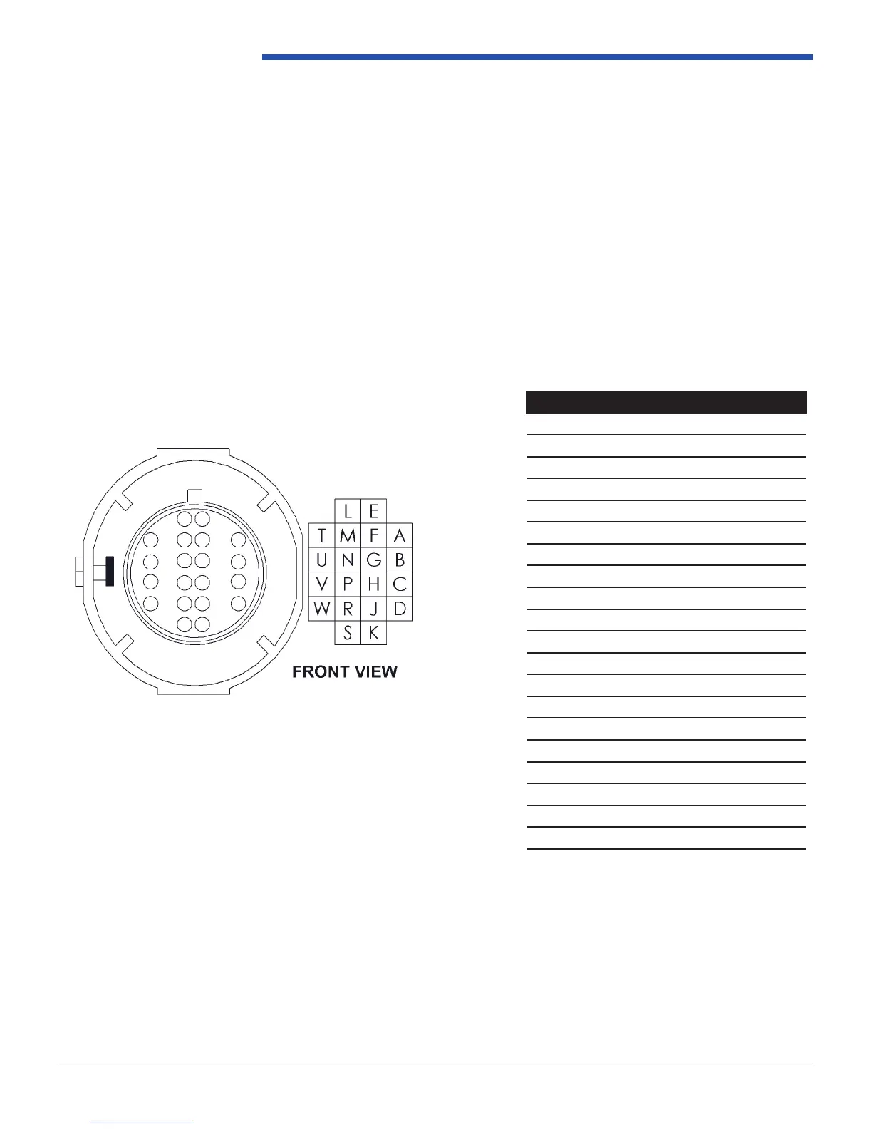
Electrical Connections
Two connections must be made to the transmission to interface with the TCM. The connections are for the transmission
control connector and the output speed sensor. Figures 1.5.2-1 and 1.5.2-2 shows the internal system schematic.
CAV Function
A Shift SOL ‘A’
B Shift SOL ‘B’
C Line Pressure +
D Line Pressure -
E Switched +12V
F IMS A
G IMS C
H IMS B
J IMS P
K Turbine Speed +
L Trans Temp Sensor
M Trans Temp Sensor Ground
N IMS Ground
P
R Forward Clutch SOL
S Reverse Clutch SOL
T TCC SOL
U TCC PWM
V Turbine Speed
W Neutral Safety
TCM Connector
Figure 1.5.2-1: TCM Connector and Terminal Locations