Page 56
Ph: 804.227.3023
10511 Old Ridge Rd. Ashland, VA 23005
4LHD/4LHDX Application Manual
Powertrain Control Solutions
REV 1.1
Transmission Range Selection System Requirements
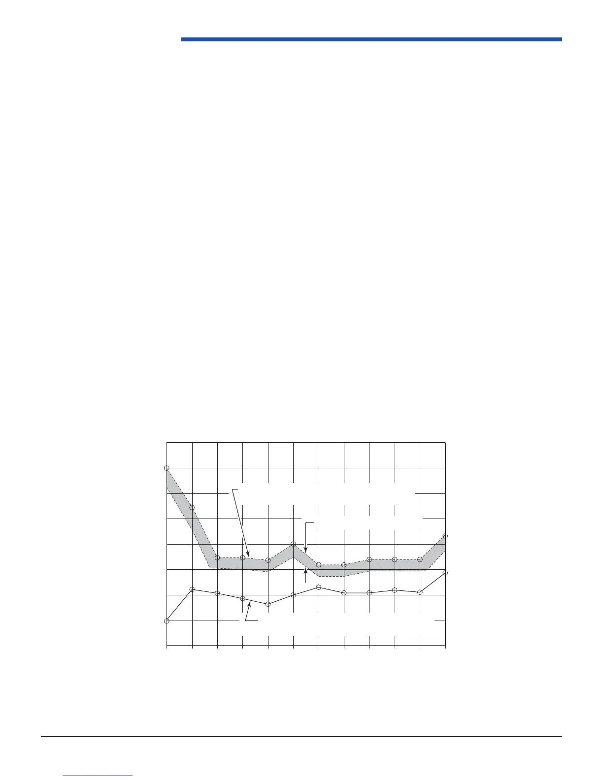
System Drag: The maximum amount of drag associated with the shifter system as seen by the transmission must be
a minimum of 0.45 Nm (4.0 in lb) lower than the detent centering torque provided by the transmission. (See following
gure.) This will enable the transmission to control the position of the range selection system within each gear range.
Transmission Range Selection System Analysis
Driver selection lever effort is found by measuring the load at the end of the selection lever. The lever is moved from Park
to Low and Low to Park with the corresponding maximum load readings recorded.
System drag is evaluated by taking torque measurements at the manual shaft nut when rotating it through the ranges.
Measurements are recorded rst to determine total system torque with the shifter gate defeated and with the shift cable/
linkage system attached to the transmission shift lever. The transmission detent centering torque is then determined by
detaching the shift cable/linkage, removing the neutral start switch and again rotating the manual shaft nut. The system
drag, as seen by the transmission, is equal to the total system torque minus the detent centering torque. The detent
centering torque must be greater than the system drag. For shifter systems which contain a detent spring in the shifter,
total system torque is measured with the cable disconnected from the shifter. The shifter detent spring must provide
greater centering torque than the drag associated with the shifter and the indicator/close-out.
Typical sources of system drag include
• Cable friction
• Neutral start switch rotating torque
• Shifter pawl to gate plate
• Indicator slide effort
• Column to dashboard closeout
• Shifter closeout
Figure 2.4.2-2 System Drag vs. Transmission Centering Torque
RevSheet 7124214609
FIGURE 3.4.3.2-1 System Drag vs. Transmission Centering Torque
R-NP-R N-D D-3 3-2 2-1 1-2 2-3 3-D D-N R-PN-R
RANGE SELECTION SYSTEM DRAG
MEASURED AT TRANSMISSION SELECTOR SHAFT
TRANSMISSION DETENT CENTERING TORQUE
MEASURED AT TRANSMISSION SELECTOR SHAFT
0.45 Nm DESIGN CONSTRAINT
RANGE POSITION