Page 43
Ph: 804.227.3023
10511 Old Ridge Rd. Ashland, VA 23005
4LHD/4LHDX Application Manual
Powertrain Control Solutions
REV 1.1
4. Pull sharply on pipe to assure a correct connection.
5. Snap plastic cap onto quick connector assembly. Do not depress the retainer clip. There should be no gap between
the cap and the quick connector hex.
6. Ensure no pipe damage occurred during the process.
7. Assure hoses/pipes are not kinked, crossed, twisted or grounded to any unspecied vehicle components. Due care
must be taken to prevent intentional movement of the cooler lines in the assembly process. Unnecessary vibration,
leakage or transmission malfunction may occur.
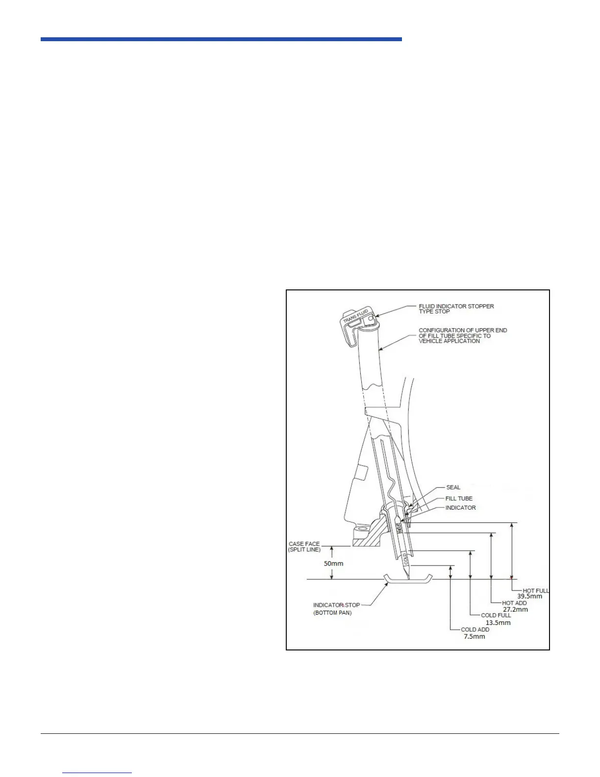
2.3.4 Dipstick
Level setting must be done by means of a dipstick type indicator. The indication hardware is attached at the time of
assembly to the engine or vehicle. The conguration of the upper end of the ll tube is specic to each vehicle, according
to vehicle packing requirements.
Based on the OEM customer preference, if an
indicator stopper type is used, it is recommended
that the words “Trans Fluid” are plainly labeled for
customer identication.
The top of the ll tube must be arranged so that any
uid expelled from the ll under extreme adverse
conditions can not fall on surfaces hot enough (e.g.
exhaust system, turbo charger, etc.) to cause ignition
of the uid.
Powertrain Control Solutions Engineering will specify
nominal indicator marking positions. These will have
been derived from the transmission’s functional uid
level limits, which are different from the indicator
markings. The procedure to develop the indicator
markings from the functional level limits must take into
account the tolerance added by the indicator stick.
The 4LHD/4LHDX system depends on the tip of the
indicator contacting the indicator stop.
The system depends on the indicator being longer
than the nominal path thru the center of the ll tube.
The extra length is taken up as wind-up within the ll
tube. The amount of extra length is determined by
tube and indicator tolerances and length, and must
be such that it covers dimensional stack, but does not
load the indicator beyond the room available within
the ll tube path.
It is the customer’s responsibility to package and
source the proper indicator tube and indicator. PCS
has common dipsticks available. Reference the PCS
OEM Parts Catalog for more information.
Figure 2.3.4-1 Fluid Level Indication