Page 42
Ph: 804.227.3023
10511 Old Ridge Rd. Ashland, VA 23005
4LHD/4LHDX Application Manual
Powertrain Control Solutions
REV 1.1
SAE J514 Dimensions
SAE Dash Size 6
Nom Tube OD (mm) 9.52
Nom Tube OD (in) 0.375
Straight Thread Size 9/16-18
Nom Pipe Size 1/8
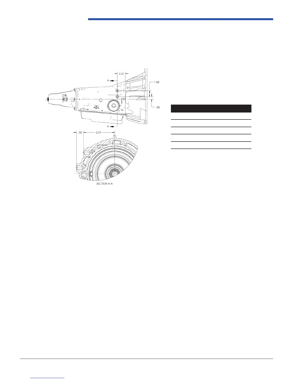
The cooler line interface exiting the case of the 4LHD/4LHDX is a #6 SAE Dash Size ORB (O-Ring Boss) for the hydraulic
tting. Reference gure 2.3.3-2 for dimensions and SAE J514 for more detailed specications.
Figure 2.3.3-2: Cooler Output Dimensions
Cooler Line Installation
The following two sections provide the general guidelines for cooler line installation.
I. Flare Type Fittings
1. Remove shipping plugs from cooler lines and ttings. Plugs should be removed as late as possible to avoid damage
or contamination of the cooler lines and ttings.
2. Loose assemble the lines to the transmission and hand start nuts. Torque as specied, 28 lb*ft / 38 N*m. Over torquing
could distress the established thread lock of the connector in the transmission case.
3. Assure hoses/pipes are not kinked, crossed, twisted or grounded to any unspecied vehicle components. Due care
must be taken to prevent intentional movement of the cooler lines in the assembly process. Unnecessary vibration,
leakage or transmission malfunction may occur.
II. Quick Connect Type Fittings
1. Remove shipping plugs from cooler lines and ttings. Plugs should be removed as late as possible to avoid damage
or contamination of the cooler lines and ttings.
2. While gripping pipe body below plastic cap, insert pipe into connector until a click is felt - DO NOT use cap to insert
pipe.
3. Ensure yellow identication band is entirely within quick connector assembly. If not, insert pipe until yellow is completely
hidden.