Page 54
Ph: 804.227.3023
10511 Old Ridge Rd. Ashland, VA 23005
4LHD/4LHDX Application Manual
Powertrain Control Solutions
REV 1.1
2.4.1 Shaft Specs
The shift lever (which is to be supplied by the vehicle manufacturer) must conform to the following specication:
Stock Thickness: 4.3 to 4.7 mm (0.169 to 0.185 in)
Hardness: Surface le hard Rc 59 min.
Case depth 0.12 to 0.25 mm (0.005 to 0.010 in)
Parts should not be brittle.
Manual shaft connection:
The interface between the manual shaft ats and the lever ats must have a press t of
0.00 to 0.13 mm (0.000 to 0.005 in).
Punch direction must be from the lead-in side.
Slot dimensions to be maintained for a minimum of 50% stock thickness from lead-in side. No burrs permissible around
slot on lead-in side.
Corrosion protection of external nut and lever required to be compatible with coating on
manual shaft.
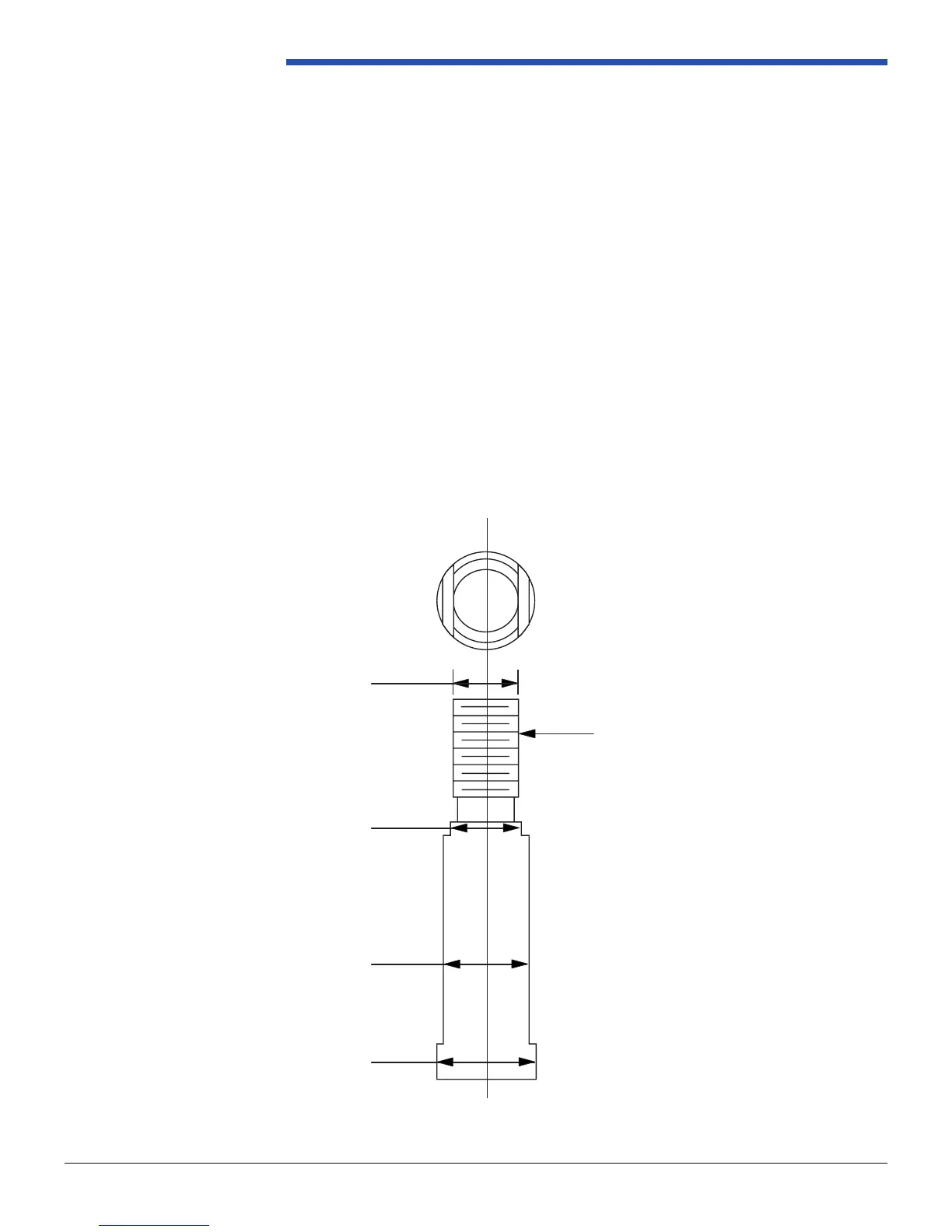
Figure 2.4.1-1 Manual Shaft Dimension
RevSheet 6924214609
3.4.2. Manual Shaft/Lever Interface
The shift lever (which is to be supplied by the vehicle assembly division) must conform to
the following specification:
Stock Thickness: 4.3 to 4.7 mm (0.169 to 0.185 in)
Hardness: Surface file hard Rc 59 min.
Case depth 0.12 to 0.25 mm (0.005 to 0.010 in)
Parts should not be brittle.
Manual shaft connection:
The interface between the manual shaft flats and the lever flats must have a press fit of
0.00 to 0.13 mm (0.000 to 0.005 in).
Punch direction must be from the lead-in side.
Slot dimensions to be maintained for a minimum of 50% stock thickness from lead-in side.
No burrs permissible around slot on lead-in side.
Corrosion protection of external nut and lever required to be compatible with coating on
manual shaft.
FIGURE 3.4.2-1 Manual Shaft Dimension
M10 x 1.5-6g
8.05 ± 0.13
10.90 ± 0.04
12.677 ± 0.010
8.40 ±
0.03
0.02