Page 66
Ph: 804.227.3023
10511 Old Ridge Rd. Ashland, VA 23005
4LHD/4LHDX Application Manual
Powertrain Control Solutions
REV 1.1
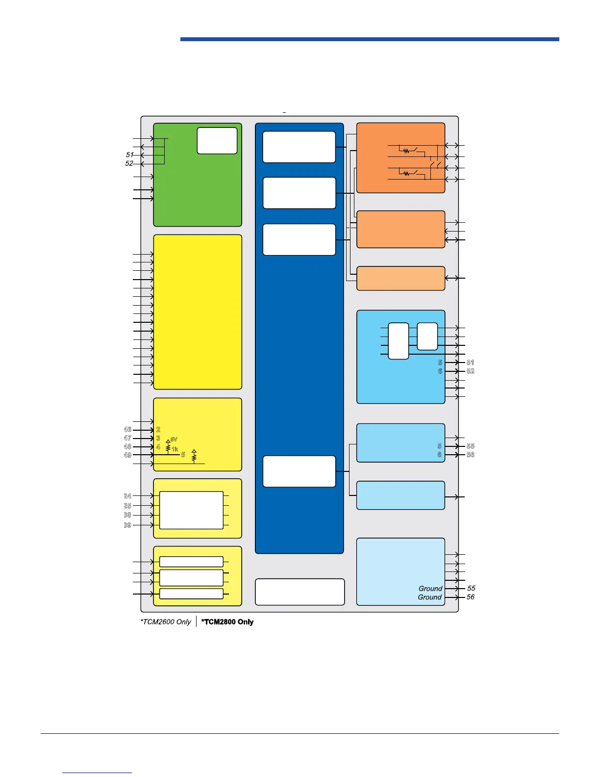
TCM2600 / TCM2800 Block Diagram
Input Power
PCS Proprietary
Transmission Controller
Embedded Operating
System v.4
PCS Core
TCM2600: v.6
TCM2800: v.7
Switched
+12V
Battery
Constant +12V
Ground
Ground
19
18
9
42
20
Digital Inputs
2
3
4
5
6
7
8
10
29
30
31
32
33
34
35
36
1
2
3
4
5
6
7
8
9
10
11
12
13
14
15
16
Programmable active high or low,
toggle or momentary
Input: 8-16 VDC
Battery
Voltage
Measurement
Zero Crossing Output
17
Digital Outputs
41
55
56
4
5
6
Sensor Reference
21
22
23
37
5V
Ground
Ground
Ground
J1850
1
Comm
Tx
Rx
Ground
26
27
28
Single Wire Diagnostic
Serial: Use TCM4181 Cable
USB: Use TCM4180 Cable
TCM2600: Low Side Drive Only
TCM2800: Programmable High
or Low Side Drive
PWM Outputs
5
6
7
8
9
1
2
3
4
11
12
13
14
51
52
53
54
40
TCM2600: Low Side Drive Only
TCM2800: Programmable High
or Low Side Drive
Programmable
Dither
Current
Measurement
OBDII Diagnostics
PCS Tuning Interface
Data Logging Interface
Speedometer Output
Analog Inputs (0-5V)
1
2
3
4
5
5V
1k
6
5V
1k
Speed Inputs: TCM 2600
1
4
Magnetic Sensor Interface
2
3
Hall-Eect Sensor Interface
Programmable trigger lter
value and1k pull-up
Speed Inputs: TCM 2800
1
2
3
4
Programmable trigger lter
value and1k pull-up
Circuit Board Temperature
Measurement
CAN 2.0B
Configurable for J1939, GMLAN, and
PCS CAN
15
CAN1 H
16
CAN1 L
43
CAN2 H
44
CAN2 L
Programmable
Bridge Mode
*
*
*
Programmable 120 Ohm terminating resistor
Rev 3 - 6/15
Figure 2.5.2-1: TCM Block Diagram