EasyManua.ls Logo

Peak Atlas LCR45 - User Manual

Peak Atlas LCR45
28 pages
Print Icon
To Next Page IconTo Next Page
Loading...
Atlas LCR45
Passive Component Impedance Meter
Model LCR45
Designed and manufactured with pride in the UK
User Guide
©
Peak Electronic Design Limited 2002-2019
In the interests of development, information in this guide is subject to change without notice - E&OE
GB45-4
electronic design ltd

Questions and Answers

  • G
    gharrisJul 28, 2025
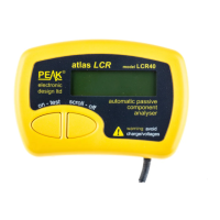
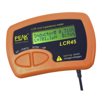
    What to do if measured value is not correct on Peak Atlas LCR45?
    • S
      shortericaJul 28, 2025
      If the measured value doesn't appear correct on your Peak LCR45 Measuring Instruments, ensure the probes are well-connected to the component under test for a few seconds, allowing the readings to stabilize. Verify that nothing else is connected to the component and avoid touching the connections during measurement. If the issue persists, the LCR45 may have selected a non-optimal mode; try a manual mode. Also, the component value may be outside the supported measurement range, or the component’s design frequency may not correspond to the test frequencies used by the LCR45.
  • C
    Cynthia CookAug 3, 2025
    Why does my Peak Measuring Instruments show that the calibration date is approaching or has passed?
    • G
      Gerald FryeAug 3, 2025
      Your Peak LCR45 Measuring Instruments will continue to function normally even after the calibration due date has passed. The calibration date is simply a recommendation.
  • T
    thomas47Aug 9, 2025
    Why do measured values vary between readings on Peak Measuring Instruments?
    • J
      jeffrey20Aug 9, 2025
      The displayed resolution on your Peak Measuring Instruments is intentionally set higher than the internal measurement resolution to minimize rounding errors. Therefore, variations within the specified measurement resolutions are normal.
  • W
    Wesley HutchinsonAug 15, 2025
    How to fix resistance or inductance measurements not close to zero on Peak Atlas LCR45?
    • A
      Adrienne WalshAug 15, 2025
      If the resistance and/or inductance measured on your Peak Measuring Instruments is not close to zero when the probes are short-circuited, perform a probe compensation.
  • P
    Patricia FoxAug 21, 2025
    What to do if capacitance measured is not near zero on Peak Atlas LCR45 Measuring Instruments?
    • T
      Travis BoydAug 21, 2025
      If the capacitance measured on your Peak Measuring Instruments when the probes are open circuit is not close to zero (±1.0pF), perform a probe compensation.

Summary

Important Notices

User Interface

Using your LCR45

Normal Use - Fully Auto Mode

Explanation of the default automatic mode for component testing.

Component Display

Describes how component type, frequency, and values are shown.

Impedance Display

Admittance Display

Magnitude and Phase Display

Measurement Screen Selection

Modes and Settings

Accessing and changing the instrument's operating modes and settings.

LCR45 Operation Mode Selection

Automatic Component Identification

Instrument automatically identifies component type and analysis.

Test Frequency Mode Selection

Automatic Test Frequency

Instrument automatically selects the most appropriate test frequency.

Testing Capacitors

Capacitor Discharge Warning

Critical advice on discharging capacitors to prevent instrument damage.

Probe Compensation

Self Tests

Appendix C - Auto Component Identification Criteria

Capacitor Detection Criteria

Resistor Detection Criteria

Appendix D - Technical Specifications

Appendix E - Troubleshooting

Peak Atlas LCR45 Specifications

General IconGeneral
TypeLCR Meter
Measurement ParametersInductance (L), Capacitance (C), Resistance (R)
Test Frequency100 Hz, 120 Hz, 1 kHz, 10 kHz
DisplayLCD
Power Supply9V Battery

Related product manuals