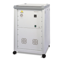
Principle of Operation
Peak Scientific Instruments NM30LA-MS The Nitrogen generator employs “Hollow Fibre
Membrane” Technology to efficiently separate Nitrogen from other gases present in
ambient air. An overview of this process can be seen below.
12
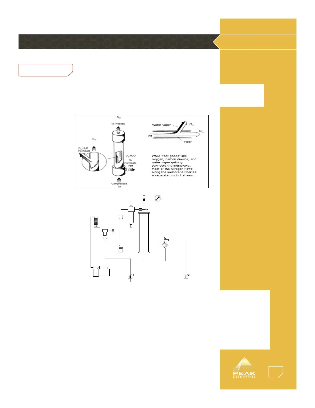
Flow Diagram
UM-NM30LA-MS Gas Generator
UM –NM30LA-MS
Pneumatic Diagram
3.
4.
8.
10.
5.
6.
11.
1.
7.
9.
2.
Air is drawn into the system by the Compressor (1) and passed through the Cooling Coil (2) and
the AFD – 3000 Micro Mist Filter (3) into the Membrane (5). After the Membrane (5) the gas is
passed through a Reverse Acting Carbon Filter (6) to remove any remaining impurities and via the
Non-Return Valve (Check Valve) (7) into the Receiver (10). The stored gas is regulated (11) to give
the required output pressure and flow. Receiver pressure is measured (9) to allow the generator to
un-load (4) and shut-down should demand cease. A Safety Relief Valve (8) is fitted to protect the
system against over pressure. Gas is delivered out of the machine via the Outlet Port (12). Any
moisture collected by the AFD – 3000 Micro Mist Filter (3) is expelled via the Drain Port (13).