The description of the Channel Menu is shown as the following list:
Function Menu Setting Description
Coupling
DC
AC
GROUND
Unblock the AC and DC components in the input signal.
Block the DC component in the input signal.
The Input signal is interrupted.
Inverted
OFF
ON
The waveform is displayed normally.
Initiate the waveform inverted function.
Probe
1X
10X
100X
1000X
Choose one according to the probe attenuation factor to
make the vertical scale reading accurate.
Limit
(only P 1245/1255/1260)
full band
20M
Get full bandwidth.
Limit the channel bandwidth to 20MHz to reduce display
noise.
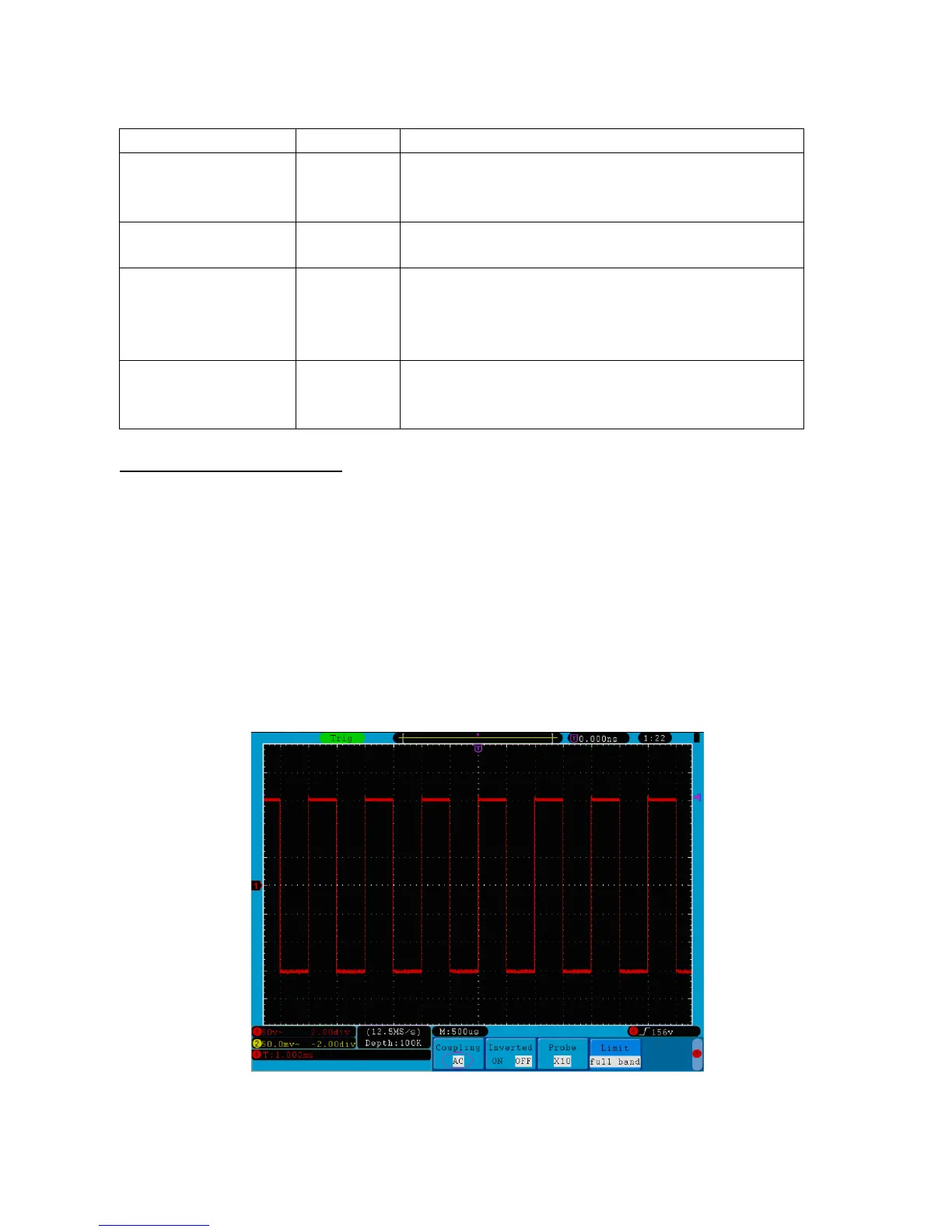
11.2. Setting Channel Coupling
Taking the Channel 1 for example, the measured signal is a square wave signal containing the direct current
bias. The operation steps are shown as below:
* Press the CH1 MENU button and call out the CH1 SETUP menu.
* Press the H1 button, the Coupling menu will display at the screen.
* Press the F1 button to select the Coupling item as “DC”. By setting the channel coupling as DC mode, both
DC and AC components of the signal will be passed.
* Then, press F2 button to select the Coupling item as “AC”. By setting the channel coupling as AC mode,
the direct current component of the signal will be blocked. The waveforms are shown as Fig. 15.
Fig. 15 AC Coupling Oscillogram
-107-