Do you have a question about the Peavey CS 3000 and is the answer not in the manual?
General safety guidelines for electrical products, including installation and usage.
Information on safe noise exposure levels and the need for hearing protection.
Instructions for inspecting the amplifier after unpacking and retaining packing materials.
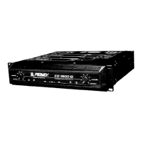
Guidance on rack mounting and using rear mounting ears for installation.
Details on the forced-air cooling system and rack mounting ventilation needs.
Essential precautions before operation, including voltage checks and power-up procedures.
Information on connecting audio sources and speakers to the amplifier.
Voltage requirements and power connection configurations for different regions.
How to configure and operate the amplifier in stereo mode for dual-channel output.
Instructions for parallel operation, using a single input to drive both channels.
Details on bridging channels for a powerful single-channel monaural output and associated precautions.
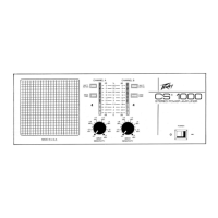
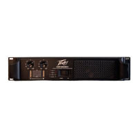
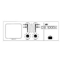
Description of the AC power switch, circuit breaker, and input attenuators.
Function of the CONN. MODE and AMP MODE select switches on the rear panel.
Explanation of the PWR, SIG, and DDT front panel LED indicators and their meanings.
How DDT limits gain to protect speakers from clipping.
Details LFC circuit for load overstress and short circuit protection.
How the amplifier protects against overheating and DC voltage on outputs.
Explanation of the mute function during power up and down to prevent thumps.
Describes the gradual signal increase on power-up to prevent speaker damage.
Important limits and considerations for speaker protection and amplifier output.
Details user responsibilities for operation, safety, and no routine maintenance required.
Guidelines for obtaining service, repairs, and warranty information.
| Signal to Noise Ratio | > 100 dB |
|---|---|
| Input Impedance | 20 kOhms Balanced, 10 kOhms Unbalanced |
| Type | Power Amplifier |
| Number of Channels | 2 |
| Frequency Response | 20 Hz - 20 kHz |
| Total Harmonic Distortion | < 0.03% |
| Dimensions | 19" x 3.5" x 12.5" (483 x 89 x 318mm) |
| Damping Factor | > 300 @ 1 kHz |