Do you have a question about the Peavey CS 4000 and is the answer not in the manual?
Details OSHA-specified permissible noise levels and the need for hearing protection.
Read important safety precautions, input, output, and power connection sections for your safety.
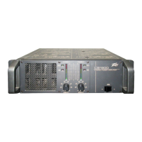
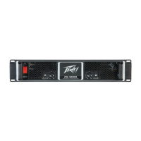
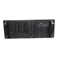
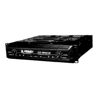
Instructions for inspecting, unpacking, and mounting the amplifier, including rack mounting.
Details on the forced-air cooling system and ensuring proper airflow for operation.
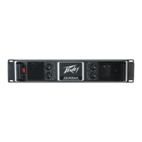
Connect inputs via three-pin XLR or 6.3 mm combi connectors on the rear panel.
Connect outputs using banana plugs, spade lugs, bare wire, or Speakon connectors.
Ensure mains voltage is correct; turn off and disconnect before making audio connections.
Channels operate independently with separate input attenuators.
Single input signal drives both channels; connectors are strapped together.
Channels bridged for powerful single-channel output; use caution with high voltage.
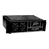
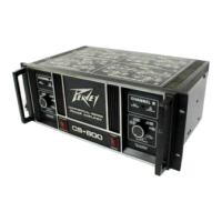
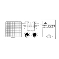
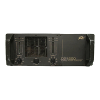
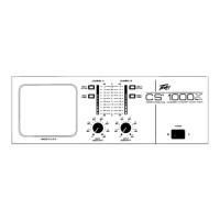
Details on AC Power Switch/Circuit Breaker, Input Attenuators, CONN. MODE, and AMP MODE switches.
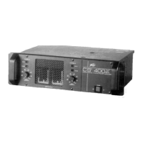
Description of rear panel connectors for inputs, outputs, and mode switches.
Explanation of the PWR, SIG, and DDT LED indicators on the front panel.
DDT circuit reduces gain to prevent speaker damage from clipping and high-power square waves.
LFC circuit adjusts gain for safe operation into any load, disconnecting if needed.
Protects against overheating, shorts, DC voltage, and prevents power transition thumps.
RampUp circuit attenuates signal on power-up/protect exit, then gradually raises it for safe audio bursts.
Protects speakers from excessive power, low frequencies, clipped waveforms, and DC voltage.
Details on returning the amplifier for service, contact information, and warranty.
| Signal to Noise Ratio | > 100 dB |
|---|---|
| Connectors Input | XLR and 1/4" TRS |
| Power Output (4 ohms) | 1350W per channel |
| Power Output (Bridged 4 ohms) | 4000W |
| Power Output (Bridged 8 ohms) | 2700W |
| Frequency Response | 20 Hz - 20 kHz |
| Total Harmonic Distortion | < 0.03% |
| Input Impedance | 20k ohms balanced, 10k ohms unbalanced |
| Cooling | Variable speed fan |
| Connectors Output | Speakon, binding posts |
| Dimensions | 3.5" x 19" x 18.5" |
| Power Output (2 ohms) | 2000 W RMS x 2 |