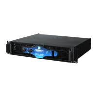
GPS 900/1500
150VAC Units Only
Channel A Input Source
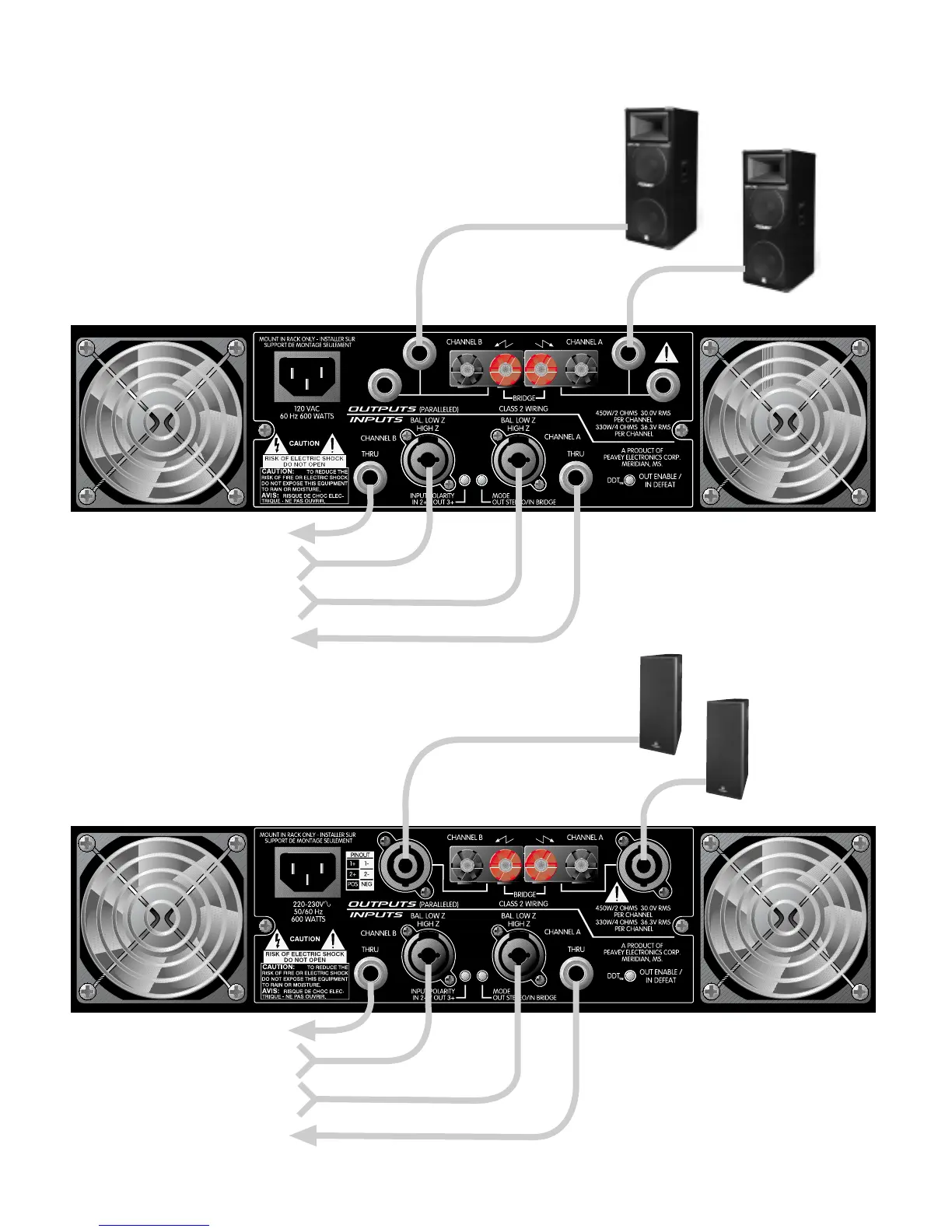
All other GPS Models
NOTE: Always use a balanced input source if available.
NOTE: Minimum Load
Impedance is 2 Ohms.
NOTE: Minimum Load
Impedance is 2 Ohms.
GPS
™
Series Amplifiers
Recommended Connection for Stereo Mode
SP
™
7G
SP
™
7G
Channel B Input Source
1/4" jacks are wired in parallel
with binding post.
Tip = Positive
Ring = Negative
DTH
®
4215F
DTH
®
4215F
Speaker connectors are wired in
parallel with binding posts.
Pins (1+) and (2+) are wired positive.
Pins (1-) and (2-) are wired negative.
To Additional Amplifier Input
To Additional Amplifier Input
Channel A Input Source
Channel B Input Source
To Additional Amplifier Input
To Additional Amplifier Input
 Loading...