46
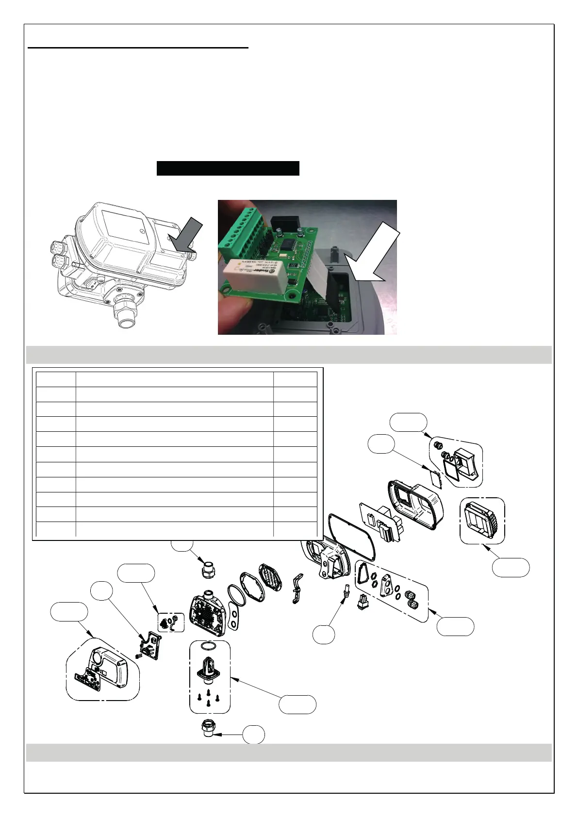
FITTING THE EXPANSION BOARD
- Switch off power to the inverter and wait 2 minutes for the capacitors discharge
- Open the back cover as shown in the figure on next page
- Insert the flat cable of the expansion board (see picture on next page) on the mating
connector mounted on the power board of the inverter
- WARNING: PAY ATTENTION TO PROPERLY FIT THE CONNECTOR
- Block the expansion board with 4 screws
- Connect signals (see SIGNALS CONNECTION.)
- Close the back cover
SPARE PARTS DIAGRAM
KIT 1
KIT 2
KIT 6
KIT 4
KIT 3
KIT 5
6
7
7
8
10
N° Description Q.ty
KIT 1 Cover Kit with keyboard 1
KIT 2 Pressure sensor Kit 1
KIT 3 Non-return valve / flow sensor Kit 1
KIT 4 Cable bushing cover Kit 1
KIT 5 Expansion board cover Kit 1
KIT 6 Capacitor box Kit 1
7 GAS
three-piece joint 1” GAS M Kit 2
7 NPT
three-piece joint 1” NPT M Kit 2
8 Fuse (only for single phase versions) 1
10 RS485 expansion board + alarms 1