6 of 26
ISSUED: 04-01-11 SHEET #: 203-9028-5 11-20-14
Installing Display Screws
To prevent scratching the display, set a cloth on a fl at, level surface that will support the weight of the display.
Place display face side down. If display has knobs on the back, remove them to allow the adapter brackets to be
attached.
NOTE: Top and bottom holes of display must always be used.
• Tighten screws so they are fi rmly attached. Do not tighten with excessive force. Overtightening can cause stress
damage to screws, greatly reducing their holding power and possibly causing screw heads to become detached.
Tighten to 40 in. • lb (4.5 N.M.) maximum torque.
• If screws don't get three complete turns in the display inserts or if screws bottom out and bracket is still not tightly
secured, damage may occur to display or product may fail.
WARNING
2
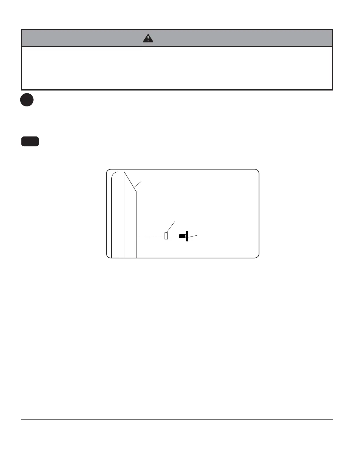
Begin with the shortest length screw (G or M) and hand thread through 1/8" spacer (O,P) into display as shown
in fi gure 2.1. Screw must make at least three full turns into the mounting hole and fi t snug into place. Do not
over tighten. If screw cannot make three full turns into the display, select a longer length screw (H or N) from the
baffl ed fastener pack. Repeat for remaining mounting holes and tighten screws.
For Flat Back Display
2-1
DISPLAY
SPACER (O,P)
SCREW (G or M)
fi g. 2.1