" i:!! ;["_e_2_
CONN£CTI_ DIAGR_
L*_[R [_AGRAM
L 1 11p_o_45_LR_1 L2
¢1 C2
FUSED RI
D'S_EC T _5_ T_I_
T ....
HIGH I
R U_IIT
2 8 R B! I I
LAD{)_R DIAGRAM L[G[NO [ 1_+41T_ __AM_ I
-- ND I
-- 120V INT_RN_L I_IR1NG I _PPILOT
-- t20v [XT_RHAL_RIN_ L _BNC)]
---- _4V iN.HAL _4RIN_
-- -- 24V [XTERNAL _I_IN_
....... _>iLOT _RIN@
o LO14_ T_R_IN_-
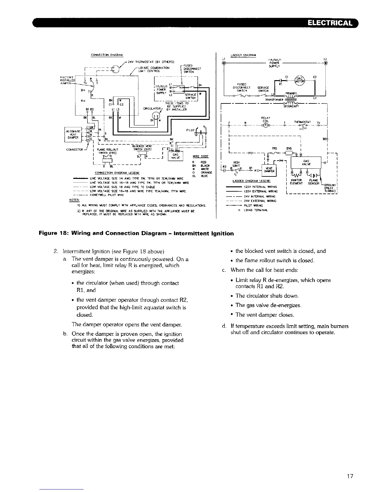
Figure 18: Wiring and Connection Diagram - Intermittent Ignition
2. Intermittent Ignition (see Figure 18 above)
a. The vent damper is continuously powered. On a
call for heat, limit relay R is energized, which
energizes:
• the circulator (when used) through contact
RI, and
• the vent damper operator through contact R2,
provided that the high-limit aqu_stat switch is
closed.
The damper operator opens the vent damper.
b. Once the damper is proven open, the ignition
circuit within the gas valve energizes, provided
that all of the following conditions are met:
• the blocked vent switch is closed, and
• the flame rollout switch is closed.
c. When the call for heat ends:
• Limit relay R de-energizes, which opens
contacts R1 and R2.
• The circulator shuts down.
• The gas valve de-energizes.
• The veat damper closes.
d. If temperature exceeds limit setting, main burners
shut off and circulator continues to operate.
17