When servicing or replacing components, be
absolutely certain that the following conditions are
met:
• Water, gas and electricity are off.
• The boiler is at room temperature.
• There is no pressure in the boiler.
OUTE ON i
// [)ARK BL JL //_\
IN CC' OR , /
1. Check flueways and burners for cleanliness and dean
if necessary. Use the following procedure if cleaning
is required:
a. Refer to the Lightin_Operating Instructions in
Figures 25 and 26 to properly turn off the gas to
the boiler.
b. Turn off all electrical power to the boiler.
c. Remove burners and brush gas outlet ports
lightly using a soft bristle brush.
d. Remove the vent pipe, vent damper, top jacket
panels and flue collector/draft diverter. Remove
baffles on MIH models.
e. Brush flueways with wire brush.
To the extent possible, inspect inside of vent pipe
and vent damper for obstructions in flow or vent
damper movement. Remove or replace as
necessa[v.
g.
Re-install baffles on MIH models. When replacing
the flue collector/draft hood, be certain that the
blanket seal between the flue collector and top
section makes a tight seal to prevent leakage of
the products of combustion.
h. Re-install the top of the jacket, vent damper and
vent pipe.
i. Re-install burners.
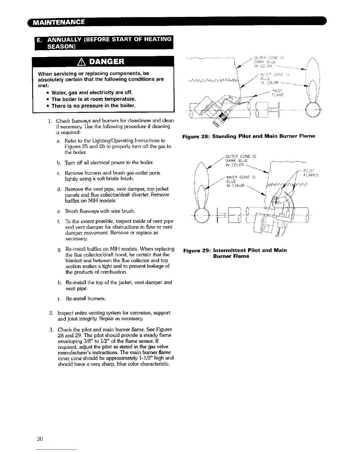
Figure 28: Standing Pilot and Main Burner Flame
INNER CONE IS
BLUE
IN COLOR
FLA_EB
Figure 29: Intermittent Pilot and Main
Burner Flame
2.
3.
Inspect entire venting system for corrosion, support
and joint integrity. Repair as necessary.
Check the pilot and main burner flame. See Figures
28 and 29. The pilot should provide a steady flame
enveloping 3/8" to i/2" of the flame sensor. If
required, adjust the pilot as stated in the gas valve
manufacturer's instructions. The main burner flame
inner cone should be approximately 1-1/2" high and
should have a very sharp, blue color characteristic.
3O