_)T[S:
l) ALL _IRINI_ MU_T COIdPLy U_T]@AP_IJ_ I_0_ _AN_ _#ID REQI3LAT_D{_
_, IT MUST _ r_':t_ClJ_ _1_ _E _ _.
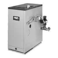
_:_IL
P_MARY W
T
(PILOT
-- l_ov _I_NG _NG )
24V W_
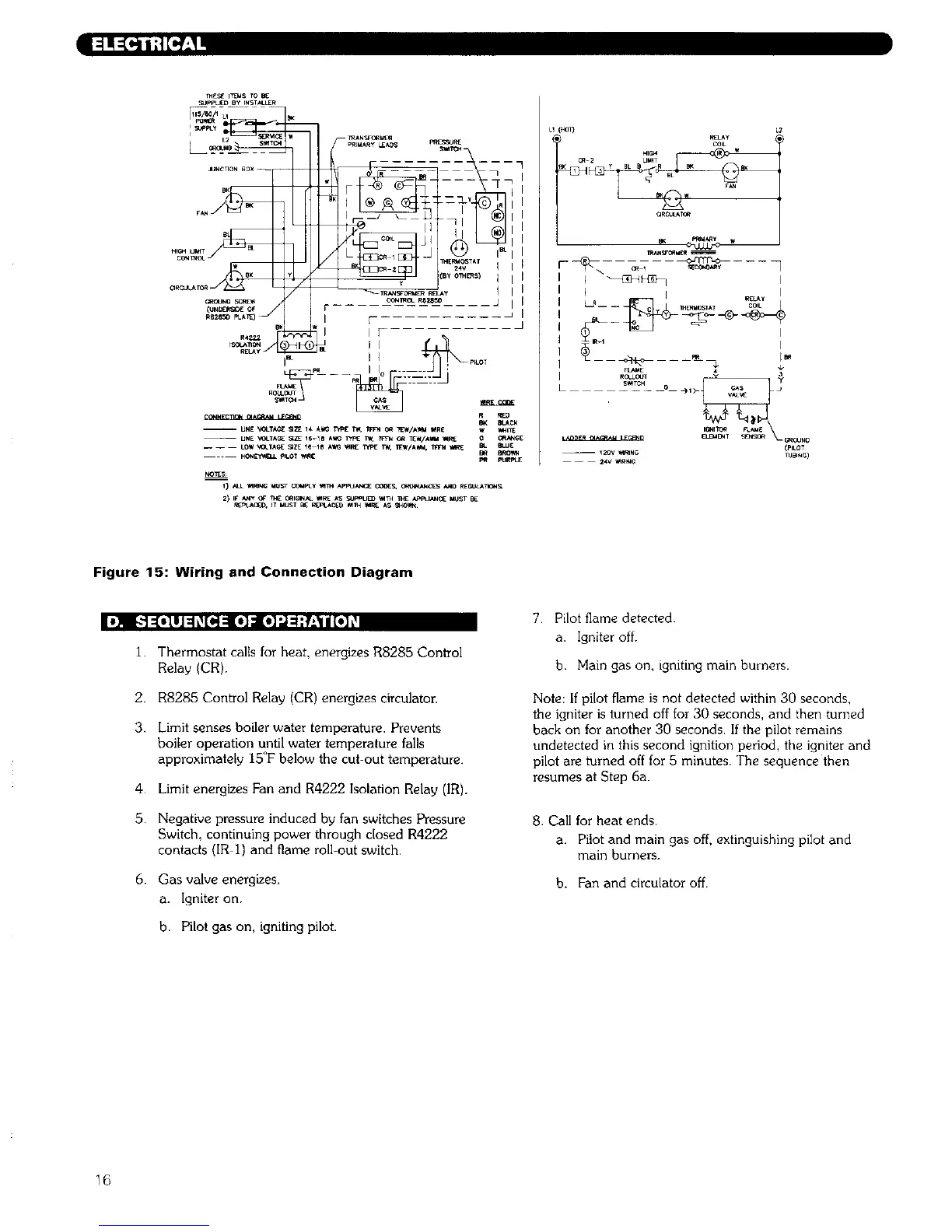
Figure 15: Wiring and Connection Diagram
[)]II _ ::[.llJ ::10[_] : [el :lt]'] :_'_:_1 i [ill _
1. Thermostat calls for heat, energizes R8285 Control
Relay (CR).
2. R8285 Control Relay (CR) energizes circulaton
3. Limit senses boiler water temperature. Prevents
boiler operation until water temperature falls
approximately 15°F below the cut-out temperature.
4. Limit energizes Fan and R4222 Isolation Relay (IR).
5. Negative pressure induced by fan switches Pressure
Switch, continuing power through c[osed R4222
contacts (IR 1) and flame roll-out switch.
6. Gas valve energizes.
a. Igniter on.
b. Pilot gas on, igniting pilot.
7 Pilot flame detected.
a. Igniter off.
b. Main gas on, igniting main burners.
Note: If pilot flame is not detected within 30 seconds,
the igniter is turned off for 30 seconds, and then turned
back on for another 30 seconds. If the pilot remains
undetected in this second ignition period, the igniter and
pilot are turned off for 5 minutes. The sequence then
resumes at Step 6a.
8. Call for heat ends.
a. Pilot and main gas off, extinguishing pilot and
main burners.
b. Fan and circulator off.
16