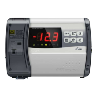
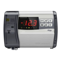
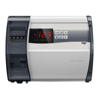
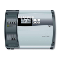
ECP200 BASE 2/4
Page 14
USE AND MAINTENANCE MANUAL
Rev. 02-09
Ald
Minimum and maximum temperature
signalling and alarm display delay
1…240 min 120 min
C1
Minimum time between shutdown and
subsequent switching on of the
compressor.
0…15 min 0 min
CAL
Cold room sensor value correction
-10…+10 0
Pc
Compressor protection contact status
0 = NO
1 = NC
0 = NO
doC
Compressor safety time for door
switch: when the door is opened the
evaporator fans shut down and the
compressor will continue working for time
doC, after which it will shut down.
0…5 minuti
0
tdo
Compressor restart time after door
opening. when the door is opened and
after tdo time, it’s setted back the normal
functioning giving door open alarm (Ed)
With tdo=0 the parameter is disabled.
0…240 min
0 = disabled
0
Fst
FAN shutdown TEMPERATURE
The fans will stop if the temperature value
read by the evaporator sensor is higher
than this value.
-45…+45°C +45°C
Fd
Fst differential
0…+10°C 2°C
LSE
Minimum value attributable to setpoint.
-45... HSE °C -45°C
HSE
Maximum value attributable to setpoint.
+45... LSE °C +45°C
tA
NO – NC alarm relay switching
0= activates when alarm is on
1= deactivates when alarm is on
1
AU
Auxiliary/alarm relay control
0
= alarm relay
1= manual auxiliary relay
controlled via AUX key
2= automatic auxiliary relay
managed by StA temp.
setting with 2°C differential
3= relay disabled / TeleNET
function
4= pump down function (see
CHAP 5.15)
5= free voltage contact for
condensing unit (AUX relay
and compressor relay in
parallel)
6= Contact for casing element
control (AUX relay closed
with compressor output
inactive).
7= relay disabled / Modbus-
RTU function
0
StA
Temp. setting for aux. relay
-45…+45°C 0
In1
Man in cold room alarm
Select input INP1 on the board as
compressor protection alarm or as man in
cold room alarm (contact NC).
0 = compressor protection
1 = man in room alarm
0
CHAP. 5 - Parameter programmin