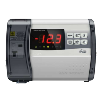
ECP202 EXPERT + BASE
Page 18
USE AND MAINTENANCE MANUAL
Auxiliary/alarm relay 1 control
-6 (NC) = relay de-energised during stand-by
-5 (NC) = Contact for casing element control
(AUX relay closed with compressor
output inactive).
-4 (NC) = pump down function (NC, see CHAP
5.16)
-3 (NC) = automatic auxiliary relay managed by
StA temp. setting with 2°C differential
(NC)
-2 (NC) = manual auxiliary relay controlled via
AUX key (NC)
-1 (NC) = alarm relay (NC)
0 = relay deactivated
1 (NO) = alarm relay (NO)
2 (NO) =manual auxiliary relay controlled via
AUX key (NO)
3 (NO) = automatic auxiliary relay managed by
StA temp. setting with 2°C differential
(NO)
4 (NO) = pump down function (NO, see CHAP
5.16)
5 (NO) = free voltage contact for condensing
unit (AUX relay and compressor relay
in parallel)
6 (NO) = relay excited during stand-by
Auxiliary/alarm relay 2 control
Temperature setting for auxiliary relay
Correction factor for the SET button
during night operation (energy saving)
(with In1 or In2 = 8 or -8)
During night operation the control set is:
Set Control = Set + nSC
In night mode decimal point flashes.
8 = Night mode digital input (energy saving,
N.O.)
7 = Stop defrosting remotely (N.O.) (reads
rising edge of impulse)
6 = Start defrosting remotely (N.O.) (reads
rising edge of impulse)
5 = Stand-by remotely (N.O.) (In order to
indicate Stand-By mode, the display shows
‘In5’ alternating with the current view)
4 = Pump-down pressure switch (N.O.)
3 = Man-in-room alarm (N.O.)
2 = Compressor protection (N.O.)
1 = Door switch (N.O.)
0 = disabled
-1 = Door switch (N.C.)
-2 = Compressor protection (N.C.)
-3 = Man-in-room alarm (N.C.)
-4 = Pump-down pressure switch (N.C.)
-5 = Stand-by remotely (N.C.) (In order to
indicate Stand-By mode, the display shows
‘In5’ alternating with the current view)
-6 = Start defrosting remotely (N.C.) (reads
falling edge of impulse)
-7 = Stop defrosting remotely (N.C.) (reads
falling edge of impulse)
-8 = Night mode digital input (energy saving,
N.C.)
CHAP. 5 - Parameter programming

 Loading...