PLUS 200 2 PLT
Page 24
Rev. 02-06
MANUALE D’USO E MANUTENZIONE
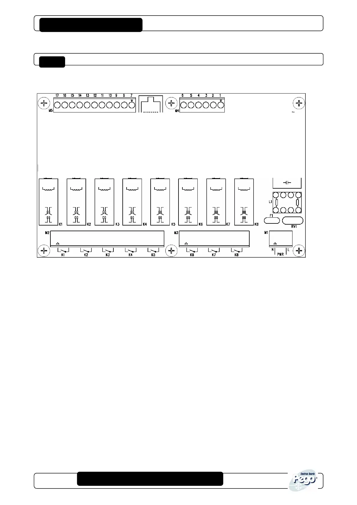
PLUS 200 2 PLT connection diagram
Power supply section
N-L Power supply 230 Vac 50 Hz
Inputs section
7-8 NTC sensor 10K, evaporator 2
9-10 NTC sensor 10K, evaporator 1
11-12 NTC sensor 10K, cold room
N.B. terminal 13 is the common of all digital inputs
13-14 Door switch
13-15 Man in cold room alarm input
13-16 Compressor protection 2
13-17 Compressor protection 1
Outputs section (no-voltage contacts)
K8 Room light
K7 General alarm
K6 System 2 defrost
K5 System 1 defrost
K4 System 2 fans
K3 System 1 fans
K2 Compressor/system 2
K1 Compressor/system 1
TeleWIN section
1-2 RS485 for TeleWIN
Allegati / Appendices
 Loading...