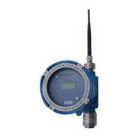
PT395 Series Detector
Follow the steps below to calibrate the sensor.
4. Remove the rain / splash guard if attached.
5. Make sure the detector and ambient air is clear of any target gas vapors. If the air
is contaminated then apply the purging (zero) air to the sensor in order to remove
the toxic vapors from the sensor head assembly. ( If zero air is applied then do not
remove air until after step 5)
6. Place the magnetic tool against the cover at 8 o’clock position to activate the
magnetic switch as shown in figure 7.
7. Place and hold the magnet until display indicates the “CAL” . Move the magnet
away from the cover.
8. While the CAL message is being displayed the sensor is making its initial
adjustments. It may take 5 to 10 seconds. (Note: Do not apply calibration gas yet)
9. Once the initial adjustments have been made, remove the zero air if applied. The
unit will display / flash the default Calibration Gas concentration or the
concentration of the calibration gas used last time. Make sure the Calibration Gas
value displayed on the LCD matches the gas concentration of the cylinder being
used for calibration. Else simply place and hold the magnet to the cover at 8
o’clock position to change the default Calibration gas concentration. Hold the
magnet at its place on the enclosure cover until the display reads the desired cal-
gas value. Refer to Table 2 below for the range of calibration gas concentration
used. The recommended calibration gas concentration is typically 50% of the full
scale range of the detector. For example, for 100 ppm H
2
S Detector, a 50 ppm H
2
S
Calibration Gas is used. The selected calibration gas value will be stored in a non-
volatile memory and remains unchanged until modified.
*** Note: For Oxygen deficiency pure nitrogen is applied as calibration gas and
thus value is not adjustable. Similarly for LEL detectors the Calibration Gas is
fixed at 50% LEL.
 Loading...