4 • FLECK 2850 Control Valve Service Manual
INSTALLATION
CONTINUED
By-Pass Valves
Always provide for the installation of a by-pass valve if unit is
not equipped with one.
Waterpressureisnottoexceed125psi(8.6bar),
watertemperatureisnottoexceed110°F(43°C),
andtheunitcannotbesubjectedtofreezing
conditions.
Installation Instructions
1. Place the softener tank where you want to install the unit
2. During cold weather, the installer should warm the valve to
room temperature before operating.
3. All plumbing should be done in accordance with local
plumbing codes. The pipe size for residential drain line
rates in excess of 7 gpm (26.5 Lpm) or length in excess of 20
feet (6 m) require 3/4-inch (19 mm) drain line. Commercial
drain lines should be the same size as the drain line
4. Refer to the dimensional drawing for cutting height of the
distributor tube. If there is no dimensional drawing, cut the
5. Lubricate the distributor o-ring seal and tank o-ring seal.
Place the main control valve on tank.
NOTE: Onlyusesiliconelubricant.
6.
For valves equipped with
electromechanical timers and stainless steel meters, refer
to the Meter Dome and Union Orientation section.
7. Solder joints near the drain must be done prior to
Leave at least 6 inches (15 cm) between the DLFC and
solder joints when soldering pipes that are connected on
the DLFC. Failure to do this could cause interior damage to
the DLFC.
8. Plumber tape is the only sealant to be used on the drain
common line.
9.
tank and that it is level.
10. Place approximately 1 inch (25 mm) of water above the grid
(Figure 1) in the salt tank. Do not add salt to the brine tank at
this time.
11. On units with a by-pass, place in by-pass position. Turn on
the main water supply. Open a cold soft water tap nearby
and let run a few minutes or until the system is free from
foreign material (usually solder) that may have resulted
from the installation. Once clean, close the water tap.
12. Slowly place the by-pass in service position and let water
open a cold water tap nearby and let run until the air is
purged from the unit.
13. Plug unit into an electrical outlet.
NOTE: Allelectricalconnectionsmustbeconnected
accordingtolocalcodes.Becertaintheoutletis
uninterrupted.
60002 Rev E
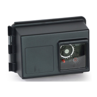
Figure 1 Residential Air Check Valve
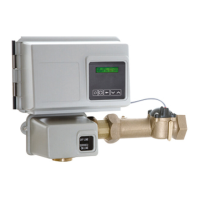
Meter Dome and Union Orientation
stainless steel water meter include a special male x female
threaded stainless steel union to insure proper installation and
operation of the water meter.
Thelocationofthisunioninrelationtothe
controlvalveandwatermeteriscriticalfor
properoperation.DONOTomitorsubstitute
thisspecialunion;itpositionsthemeterdome
atthecorrectdistancefromthecontrolvalve
andallowsre-positioningthewatermeterdome
forproperoperation.
1. Apply a suitable thread sealant to the male threads of the
union and meter body.
2. Thread the union into the OUTLET port of the control valve,
then thread the meter into the union. See illustrations on
page 5.
3. Rotate the water meter body so the meter dome is at the
this if required. Once in position, tighten the union nut.
4. Connect the meter cable to the open port in the center of the
meter dome.
5. Continue with the installation of the control valve.