FLECK 2850 Control Valve Service Manual • 3
JOB SPECIFICATION SHEET
Job Number: ___________________________________________________
Model Number: _________________________________________________
Water Hardness: ________________________________________________
ppm or gpg
Capacity Per Unit: ______________________________________________
Mineral Tank Size: _____________ Diameter: ________
Height: __________
Salt Setting per Regeneration: ____________________________________
1. Type of Timer:
A. 7 Day or 12 Day
B. Meter Initiated
2. Downow: Upow UpowVariable
3. Meter Size:
A. 3/4-inch Std Range (125 - 2,100 gallon setting)
B. 3/4-inch Ext Range (625 - 10,625 gallon setting)
C. 1-inch Std Range (310 - 5,270 gallon setting)
D. 1-inch Ext Range (1,150 - 26,350 gallon setting)
E.
F.
G. 2-inch Std Range (1,250 - 21,250 gallon setting)
H. 2-inch Ext Range (6,250 - 106,250 gallon setting)
I. 3-inch Std Range (3,750 - 63,750 gallon setting)
J. 3-inch Ext Range (18,750 - 318,750 gallon setting)
K. Electronic ____Pulse Count ___ Meter Size ____________
4. System Type:
A. System #4: 1 Tank, 1 Meter, Immediate, or Delayed Regeneration
B. System #4: Time Clock
C. System #4: Twin Tank
D. System #5: 2-5 Tanks, Interlock Mechanical
2-4 Tanks, Interlock Electronic
Meter per unit for Mechanical and Electronic
E. System #6: 2-5 Tanks, 1 Meter, Series Regeneration, Mechanical 2-4
Tanks, 1 Meter, Series Regeneration, Electronic
F. System #7: 2-5 Tanks, 1 Meter, Alternating
Regeneration,Mechanical 2 Tanks only, 1 Meter,
Alternating Regeneration, Electronic
G. System #9: Electronic Only, 2-4 Tanks, Meter per Valve, Alternating
H. System #14: Electronic Only, 2-4 Tanks, Meter per Valve. Brings
5. ValveOperatingParameters:
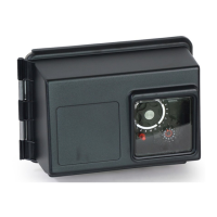
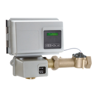
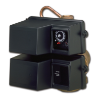
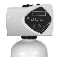
Models:2500,2510,2750,2850
Minimum operating pressure: 20 psi / 1.4 bar / 138 kPa
Maximum operating pressure: 125 psi / 8.61 bar / 861 kPa
Minimum water temperature: 34° F / 1° C
Maximum water temperature: 110° F / 43° C
Maximum Ambient temperature: 120° F / 52° C
Maximum humidity: 75%
Input Voltage: 120 Volts AC / 60 Hz
Maximum Watts: 30 watts
Maximum altitude: 2000 meters
6. TimerProgramSettings:
A. Backwash: Minutes
B. Brine and Slow Rinse: _________________________ Minutes
C. Rapid Rinse: _________________________________ Minutes
D. _____________________________ Minutes
E. Pause Time: _________________________________ Minutes
F. Second Backwash: ____________________________ Minutes
7.DrainLineFlowControl: gpm
8.BrineLineFlowController: gpm
9. Injector Size#:
10.Piston Type:
A. Hard Water Bypass
B. No Hard Water Bypass
INSTALLATION
Water Pressure
A minimum of 20 pounds (1.4 bar) of water pressure is required
for regeneration valve to operate effectively.
Electrical Warnings & Caution Statement
An uninterrupted alternating current (A/C) supply is required.
NOTE: Othervoltagesareavailable.Pleasemakesureyour
voltagesupplyiscompatiblewithyourunit
beforeinstallation.
Grounding Instructions
This appliance must be grounded. In the event of a malfunction
or breakdown, grounding will reduce the risk of electric shock
by providing a path of least resistance for electric current. This
appliance is equipped with a cord having an appliance-grounding
conductor and a grounding plug. The plug must be plugged
into an appropriate outlet that is installed and grounded in
accordance with all local codes and ordinances.
Improperconnectionoftheappliance-
groundingconductorcanresultinarisk
ofelectricshock.Checkwithaqualied
electricianorservicerepresentativeifyou
areindoubtwhethertheapplianceisproperly
grounded.Donotmodifytheplugprovidedwith
theappliance;ifitwillnotttheoutlet,havea
properoutletinstalledbyaqualiedtechnician.
Riskofelectricshock.Disconnectpowerbefore
servicing.
FOR DRY LOCATIONS USE ONLY.
The cover should only be removed during installation set-up and
Existing Plumbing
Condition of existing plumbing
should be free from lime and
iron buildup. Piping that is built
up heavily with lime and/or iron
should be replaced. If piping is
clogged with iron, a separate
ahead of the water softener.
Location of Softener and Drain
The softener should be located close to the drain to prevent air
should be two (2) times the diameter of the drain line pipe but
must be at least 1-inch.
Air Gap
Drain

 Loading...