9
L-1599 (04-01-22)
OPERATIONS & MAINTENANCE
12. Apply an anti-seize compound to engine, motor, or
pedestal shaft.
13. Install gas engine, c-faced electric motor, or pedestal
into pump drive sleeve. Align keyway of drive source
with slot in drive sleeve. Do not rotate the pump shaft
during assembly. This may cause the shim to become
dislodged.
14. Install (4) mounting bolts between pump adapter and gas
engine, electric motor, or pedestal (Figure 10).
2” pump – 5/16 x 24 screw – 11 ft.-lbs./ 14.9 Nm torque.
3” pump – 3/8 x 16 screw – 20 ft.-lbs./ 27.1 Nm torque.
15. Alternately tighten clamp bolts to ensure even torque
and balance.
2” pump – 5/16 x 18 screw – 20 ft.-lbs./ 27.1 Nm torque.
3” pump – 3/8 x 16 screw – 40 ft.-lbs./ 54.2 Nm torque.
16. Remove shim stock from pump outlet.
17. Pump and drive source should rotate freely.
DISASSEMBLY INSTRUCTIONS GAS ENGINE, C-FACED ELECTRIC
MOTOR, OR PEDESTAL MOUNT
1. Remove two-bolt clamp and bolts (Figure 11).
2. Remove (4) mounting bolts between pump adapter and
engine, motor, or pedestal (Figure 12).
3. Remove engine, motor, or pedestal. Drive source may
need to be pried off. Use caution not to damage drive
source or pump.
4. Remove (6) nuts and lock washers holding adapter to
pump (Figure 13). Mechanical seal will be exposed after
adapter is removed. Be careful not to damage seal
faces.
5. Gently pry the adapter flange off using a pry bar against
tabs on the adapter (Figure 14).
6. Remove impeller, drive sleeve, mechanical seal
assembly.
7. Remove paper gasket and discard. Remove any gasket
residue from adapter and pump faces.
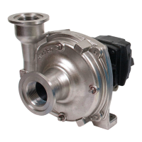
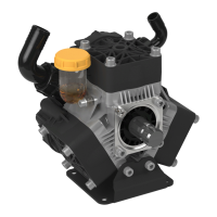
Figure 9
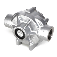
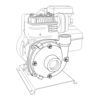
Figure 10
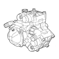
Figure 11 Figure 12
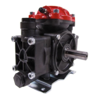
Figure 13
Figure 14
 Loading...