4
Assembly Instructions
INITIAL ASSEMBLY – gas engine, C-faced electric motor, or ped-
estal mount
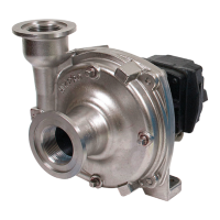
Note: Prior to assembly, visually inspect pump outlet for impeller
spacer. Pumps are supplied with a metal shim inserted into the pump
outlet and across the impeller face to ensure proper impeller spacing.
If the shim is in place, proceed to step 10. If shim is missing, begin with step
1. (Figure 1)
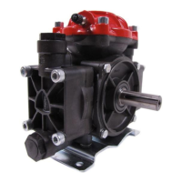
1. Remove two-bolt clamp from pump shaft. (Figure 2)
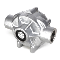
2. Remove (6) nuts and lock washers holding adapter to pump. (Figure 3)
Note: When removing adapter, be careful not to damage paper gasket between
adapter and pump.
Note: Mechanical seal will be exposed after adapter is removed. Be careful not
to damage seal faces.
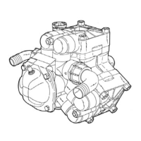
3. Gently pry the adapter flange off using a pry bar against tabs on the adapter.
(Figure 4)
4. Leave paper gasket on pump over mounting studs. If gasket is damaged,
replace with a new one. Gasket sealant is not required.
5. Remove impeller, drive sleeve, mechanical seal assembly.
6. Insert a shim between the impeller vanes and pump wear plate. A shim 1/2”
wide and 0.040” to 0.050” thick is required. Verify thickness prior to use. Place
shim material into the pump through the outlet port. Shim material must lie
across the wear plate. (Figure 5)
7. Reinstall impeller assembly ensuring the impeller vanes rest on the shim
material.
8. Reinstall adapter flange over mounting studs.
9. Tighten (6) nuts and lock washers. (Figure 6)
A. 2” pump – 5/16 x 18 nut – 11 ft.-lbs./ 14.9 Nm torque.
B. 3” pump – 3/8 x 16 nut – 20 ft.-lbs./ 27.1 Nm torque.
Note: If impeller spacer is in place, start here.
10. Install two-bolt clamp over drive sleeve. Be careful to ensure keyed portion of
Fig. 1
Fig. 2
Fig. 3
Fig. 4
Fig. 5

 Loading...