20
L-1600 (04/01/21)
MEDIUM PRESSURE 20-40 BAR INSTALLATION
INSTALLATION INSTRUCTIONS FOR GEAR REDUCTION KIT
9915-KIT1103 (REFER TO FIGURE 10)
NOTE: Hypro recommends a blue thread locking compound on
all threaded fasteners that do not require lock washers. Shaft
key needs to be inspected occasionally and replaced if worn.
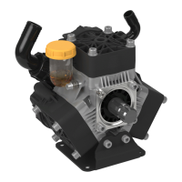
The 9915-KIT1103 gear reducer is designed for direct mounting
diaphragm pumps (listed in chart on page 19) onto a 5 hp gasoline
engine with a flange mounting and 3/4” solid shaft.
Assembly Instructions (Refer to Figure 10)
1. Take out from the pump the retaining ring sheet with the 4
corresponding fastening bolts.
2. Fasten the gear (Ref. 14) to the pump shaft by using the
corresponding 3 bolts (Ref. 13) with torque 16.2lbf [22Nm].
3. Install the O-ring (Ref. 15) in the corresponding slot on the
gear casing (Ref. 7), then fit the gear casing to the pump
tightening he bolts M10x20 (Ref. 11) with torque 29.5lbf
[40Nm].
4. Screw the oil drain plug (Ref. 9) with the proper washer (Ref.
8) and the oil sight (Ref. 12), then fill the gearbox casing with
oil SAE 80-W90 up to the middle of the oil sight. Then install
the oil filling plug (Ref. 10).
5. Insert the key (Ref. 2) the engine shaft and fit the centering
ring (Ref. 1) on the gear casing.
6. Install the “pump-gearbox assy” on the engine and tighten
the 4 corresponding bolts (Ref. 6) with torque 16.2lbf
[22Nm].
INSTALLATION INSTRUCTIONS FOR GEAR REDUCTION KIT
9915-KIT1105 (REFER TO FIGURE 11)
Hypro recommends a blue thread locking compound on all
threaded fasteners that do not require lock washers. Shaft key
needs to be inspected occasionally and replaced if worn.
The 9915-KIT1105 gear reducer is designed for direct mounting
the diaphragm pumps (listed in chart on page 19) onto an 8 hp
gasoline engine with a flange mounting and 1” solid shaft.
Assembly Instructions (Refer to Figure 11)
1. Take out from the pump the retaining ring locking sheet
with the 4 corresponding fastening bolts.
2. Install the O-ring (Ref. 9) in the half casing slot (pump side)
(Ref. 19), then fit to the pump with the 4 corresponding with
the 4 copper washer (Ref. 18) and bolts (Ref. 8) with torque
29.5lbf [40Nm].
3. Fit the ring gear (Ref. 17) to the pump shaft by using the
corresponding screws (Ref. 15) and the proper safety
washers (Ref. 16) with torque 29.5lbf [40Nm] along with
thread sealant. In case the gearbox is fixed by M8 screws
(ref. 20-21-22), tightening torque is 16.2 lbf [22Nm].
4. Screw the oil sight (Ref. 14) in the lateral part of the gearbox
casing (Ref. 12).
5. Apply sealant on the top of the 2 half casings and install the
engine side assembly on the pump side assembly. Fit the
paper gasket (Ref. 13) between the 2 assemblies and fasten
the whole system with corresponding bolts (Ref. 10) with
torque 16.2lbf [22Nm].
6. Insert the key (Ref. 1) onto the engine shaft, fit the pump-
gearbox assy to the engine and tighten the 4 corresponding
bolts 3/8” (Ref. 6) and spring washers (Ref. 5) with torque
29.5lbf [40Nm].
7. Fill the gearbox casing with SAE 80-W90 oil, up to the
middle of the oil sight, then install the oil vent plug (Ref. 11).
 Loading...