MASTERTEMP 125 Pool and Spa Heater Installation and User’s Guide P/N 475114 Rev. F 8/2020
4 |
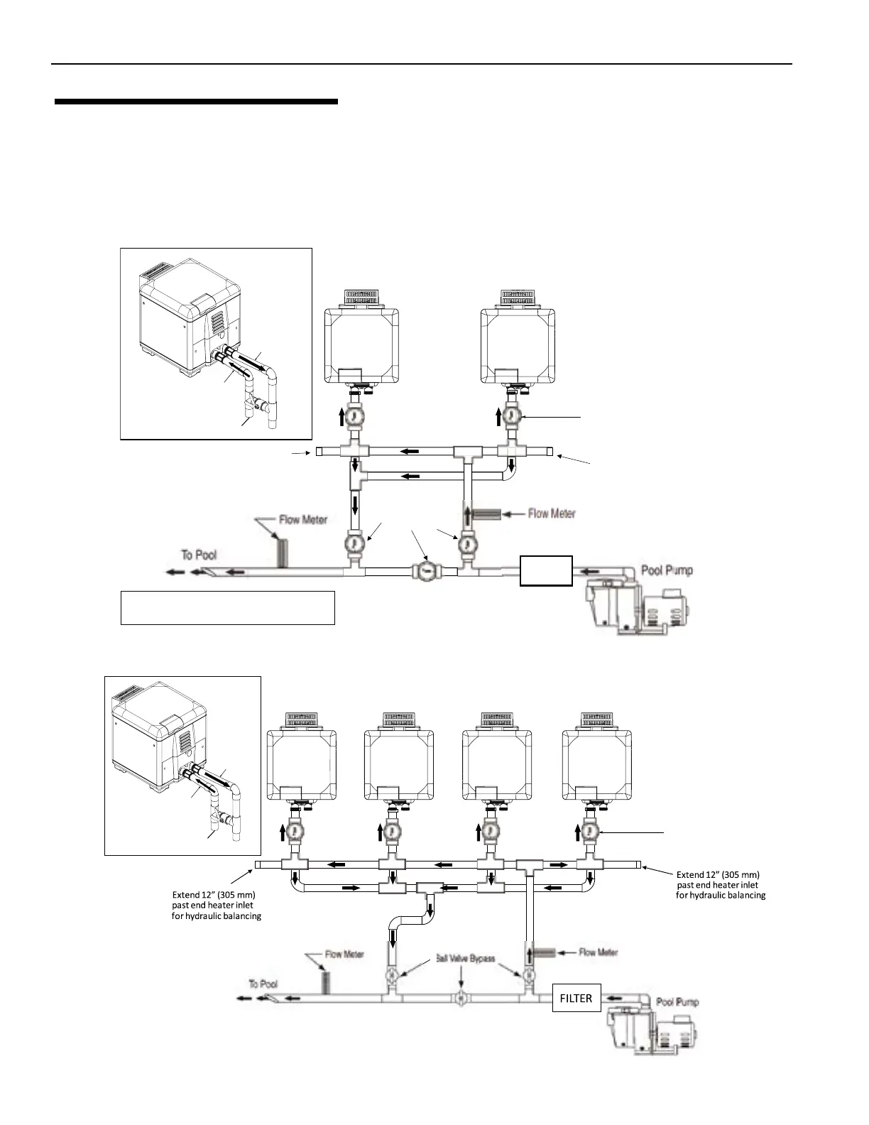
Check Va
are optional on heater inlets
but help with system
balancing
Figure 6. Four MasterTemp® 125 Heaters Plumbing Hydraulic Diagram
INLET PORT
(COLD WATER)
OUTLET PORT
(HOT WATER)
OUTLET TO POOL
INLET FROM
PUMP/FILTER
OUTLET
TO POOL
OUTLET
TO POOL
OUTLET
TO POOL
OUTLET
TO POOL
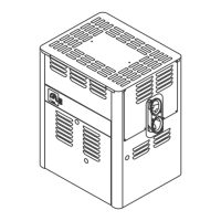
All plumbing on multiple heater installations must be done in parallel. See Figure 5 and Figure 6.
To prevent heater overheating and to ensure heater longevity, water ow to each heater must be balanced for
optimum operation. To meet recommended ow rates, be sure all installed pipes are installed in accordance with local
and state codes. To allow for proper operation and service clearance, maintain spacing to adjacent heaters. Heaters
installed too close to one another may encounter operational issues associated with exhaust fumes.
MULTIPLE HEATER INSTALLATION
OPTIONAL
2" Ball Valve Bypass
Extend 12” (305 mm)
past end heater inlet
for hydraulic balancing
Extend 12” (305 mm)
past end heater inlet
for hydraulic balancing
Figure 5. Two MasterTemp® 125 Heaters Plumbing Hydraulic Diagram
FILTER
Check Valves and Flow Meters
are optional on heater inlets
but help with system
balancing
INLET PORT
(COLD WATER)
OUTLET PORT
(HOT WATER)
60-80 GPM/Unit (recommended).
Balance flow to each heater.
OUTLET TO POOL
INLET FROM
PUMP/FILTER
OUTLET
TO POOL
OUTLET
TO POOL
Section 1. Installation