P/N 475114 Rev. F 8/2020 MASTERTEMP 125 Pool and Spa Heater Installation and User’s Guide
| 21
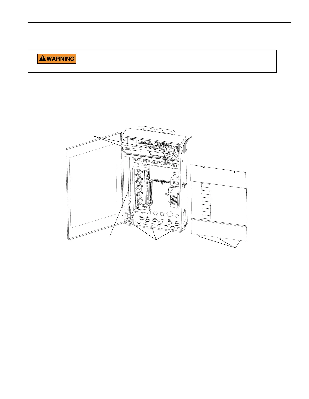
LOW VOLTAGE
RACEWAY
HigHighHigh Voltage Cover Panel Tabs (3)
Front door
HiHigh Voltage Cover Panel slots (3)
Flip down the Outdoor Control Panel to ac-
Circuit board and low
voltage compartment
Loosen Outdoor Control Panel
Retaining screws
Figure 29.
To connect the MasterTemp heater to the load center:
BEFORE REMOVING THE HIGH VOLTAGE COVER PANEL FROM THE
LOAD CENTER OR POWER CENTER ENCLOSURE SWITCH OFF THE
POWER AT THE HOUSE MAIN CIRCUIT BREAKER BOX.
1. Switch OFF AC power to the enclosure at the main house panel circuit breaker.
2. Unlatch the front door latch and open the front door. Remove the two retaining screws from the High Voltage
Cover Panel and remove the panel. See Figure 33.
3. Loosen the two retaining screws securing from the top edge of the Outdoor Control Panel. Fold down the
Outdoor Control Panel to access the circuit board sockets connectors for the electrical connections.
Connecting the RS-485 Cable from the Heater to the Load Center
Note: Use a 22 AWG four conductor low voltage RS-485 cable to connect to the MasterTemp heater to the
IntelliCenter Control System Load Center:
4. Run the RS-485 cable from the heater’s control board RS-485 COM port terminal connector to the Load
Center or Power Center. See wiring connection Figure 30 on next page.
5. Insert the cable into the one of the plastic grommet fittings, located on the lower left side of the enclosure and
pull the cable up through the low voltage to the circuit board, as shown below.
6. Strip back the outer jacket four inches. Strip back each conductor ¼-inch.
7. IntelliCenter Control System COM Port (J4 or J5): Insert the conductors into the COM Port screw terminals
located on the top of the IntelliCenter Control System circuit board (see diagram below). Secure the
conductors with the screws. For wiring details, refer to the pin configuration shown below. Note: Multiple
conductors may be inserted into a single screw terminal.
Section 1. Installation