MASTERTEMP 125 Pool and Spa Heater Installation and User’s Guide P/N 475114 Rev. F 8/2020
20 |
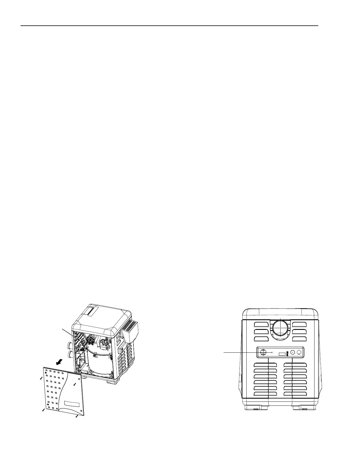
MasterTemp Heater (Exhaust Side)
Drill an appropriate size hole
for the flexible conduit or
strain relief to be used
for a flexible conduit or
strain relief to secure the
RS-485 wires
Figure 27.
Figure 28
Accessing the MasterTemp
Heater RS-485 COM Port
To access the MasterTemp heater control panel RS-485 COM port terminal, the RS-485 cable must be routed through
the hole in the heater’s side panel.
To route the RS-485 cable through the heater’s panel to the control panel circuit board:
1. Remove the four corner wing nuts that secure the top panel. Lift the top panel upward to remove the top panel. Note: If
needed, remove the wires from the control board if the top is removed completely. See Figure 27.
2. Locate the small hole in the exhaust panel, for the RS-485 cable. Use an appropriate size drill bit for the flexible conduit or
strain relief to be used in the exhaust panel to drill a hole for the RS-485 wires. See Figure 28.
3. Install a flexible conduit or a strain relief and securely attach to the heater panel. Note: The conduit or cable connector
should contain an insulating bushing or its equivalent to prevent abrasion of the RS 485 wires as it enters the exhaust
panel.
4. Strip back the outer jacket four inches of the cable. Strip back each conductor a ¼-inch.
5. Insert the RS-485 cable (from the Load Center or Power Center) through the flexible conduit or a strain relief into the
exhaust panel hole and securely attach to the heater panel.
6. Once the cable is inside the heater, route the RS-485wires under exhaust. Note: Do not let the wires contact the exhaust.
7. Using cable ties, secure to the RS-485 cable to the main wire harness that connects to heater’s control panel circuit board.
8. Insert the three RS-485 wires (Pin 1-BLK, 2-GRN, 3-YEL) into the screw terminal. Secure the conductors with the screws.
For wiring details, refer to the pin configuration on next page.
9. Heater Control Panel COM Port (J4): Insert the RS-485 connector onto the heater’s control panel RS-485 COM Port screw
terminal. Note Pin 1 is located on the right side of the terminal connector (right side edge from the back of the circuit
board).
10. Replace the top panel onto the heater side panels. Be sure that there are no wires caught under the panel. Secure the top
panel using the four corner wing nuts.
11. Continue with “Connecting the RS-485 Cable from the Heater to the Load Center” on next page.
Connecting the MasterTemp
Heater to the IntelliCenter™ Control System
Load Center via RS-485
For remote control and monitoring, the MasterTemp heater can be connected via the heater’s RS-485 COM port to the
IntelliCenter Control System COM port. The heater can be wired to the IntelliCenter Control System via a RS-485
connection. Up to 16 heaters can be connected. The default address of a heater is 1. If additional heaters are connected,
each heater must have its own address. The address range is 1 to 16. The address for each heater is set from the heater’s
front LCD panel menus.
When a heater is being controlled via the RS-485 interface: • The heater front panel buttons are inactive. Press a
panel button to turn on the LCD display. “RS485 Control” is displayed. • Heater Alarms/Errors are displayed on
IntelliCenter’s control panel(s) Status Home screen.
Section 1. Installation