MASTERTEMP
™
Pool and Spa Heater Installation and User’s Guide P/N 475106 Rev. A 2/2014
18 | Section
2. Install the metal Flue Collar in the Vent Body of
the heater (located under the outside vent cover).
Fasten the metal Flue Collar to the Vent Body
with two #10 sheet metal screws. Use high
temperature silicone RTV to seal the Flue Collar
to the Vent Body. Before connecting the metal
Flue Collar to the Vent Body, wet a clean cloth or
paper towel with isopropyl alcohol (rubbing
alcohol) and vigorously wipe the socket of the Vent
Body. Immediately wipe the cleaned surfaces dry
with a clean cloth or paper towel. Repeat for the
exterior of the 100 mm (4") end of the metal Flue
Collar. Attach the metal Flue Collar to the Vent
Body using the RTV supplied with the kit,
following the vent manufacturer’s instructions
(included with kit).
3. Attach the vent pipe to the metal Flue Collar with
sheet-metal screws.
WARNING
Risk of fire or asphyxiation if vent is not
assembled according to manufacturer’s
instructions or if vent parts from different
manufacturers are mixed. Vent parts from different
manufacturers ARE NOT interchangeable. Mixing
parts from more than one manufacturer may cause
leaks or damage to vent. When assembling a vent,
pick one manufacturer and be sure that all vent parts
come from that manufacturer and are specified by
the manufacturer for your system. Follow
manufacturer’s instructions, local code requirements
and local code standards carefully during assembly
and installation.
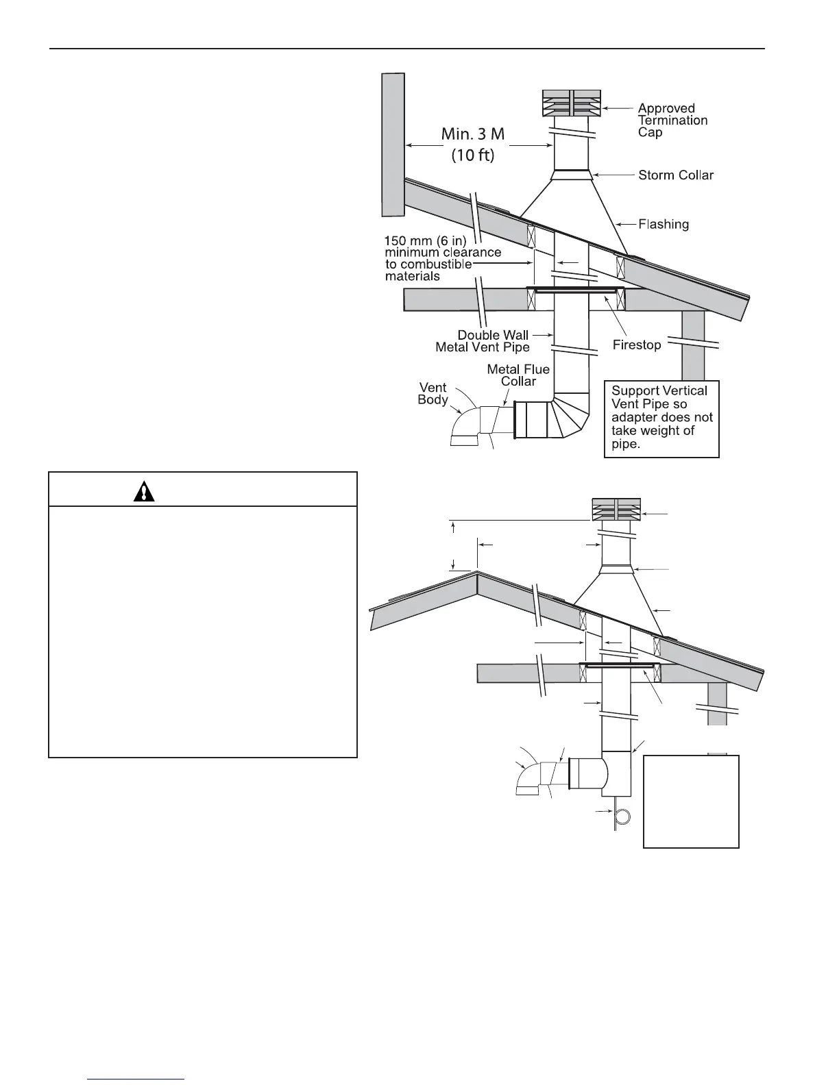
6" (15 cm) Minimum
Clearance to Combustible
Materials
Approved
Ter mination
Cap
Storm Collar
Flashing
Firestop
Vent
Body
Metal Flue
Collar
Double Wall
Metal Vent Pipe
Min. 10 Ft. (3.3 M)
Support Vertical
Vent Pipe so
adapter does not
take weight of
pipe. Dispose
of condensate
according to
local codes.
Double Wall
Metal Vent Te e
Condensate
Drain w/trap
Min. 2 Ft.
(.7 M)
Figure 22. – Typical Metal Vent Pipe Installation
(Vertical Venting)
4. Install vent pipe so that it can expand and contract freely as the temperature changes. Support the vent pipe according
to applicable codes and the vent manufacturer’s instructions. Pipe support must allow the vent pipe free movement
out and back, from side to side, or up and down as necessary, without putting a strain on the heater or vent body. Slope
horizontal pipe down to condensate trap at least 2 cm per meter (1/4 in per foot). Install approved condensate drains
at low points where condensate might collect. Plumb condensate drains to a drain through hard piping or high temperature
tubing such as silicone rubber or EPDM rubber – do not use vinyl or other low temperature tubing. Follow drain
manufacturer’s installation instructions.
2. Installation
Figure 21
1. See page 17 for Step 1 (See Table 6 to determine
allowable vent sizes for your heater.)
 Loading...