P/N 475106 Rev. A 2/2014 MASTERTEMP
™
Pool and Spa Heater Installation and User’s Guide
| 25
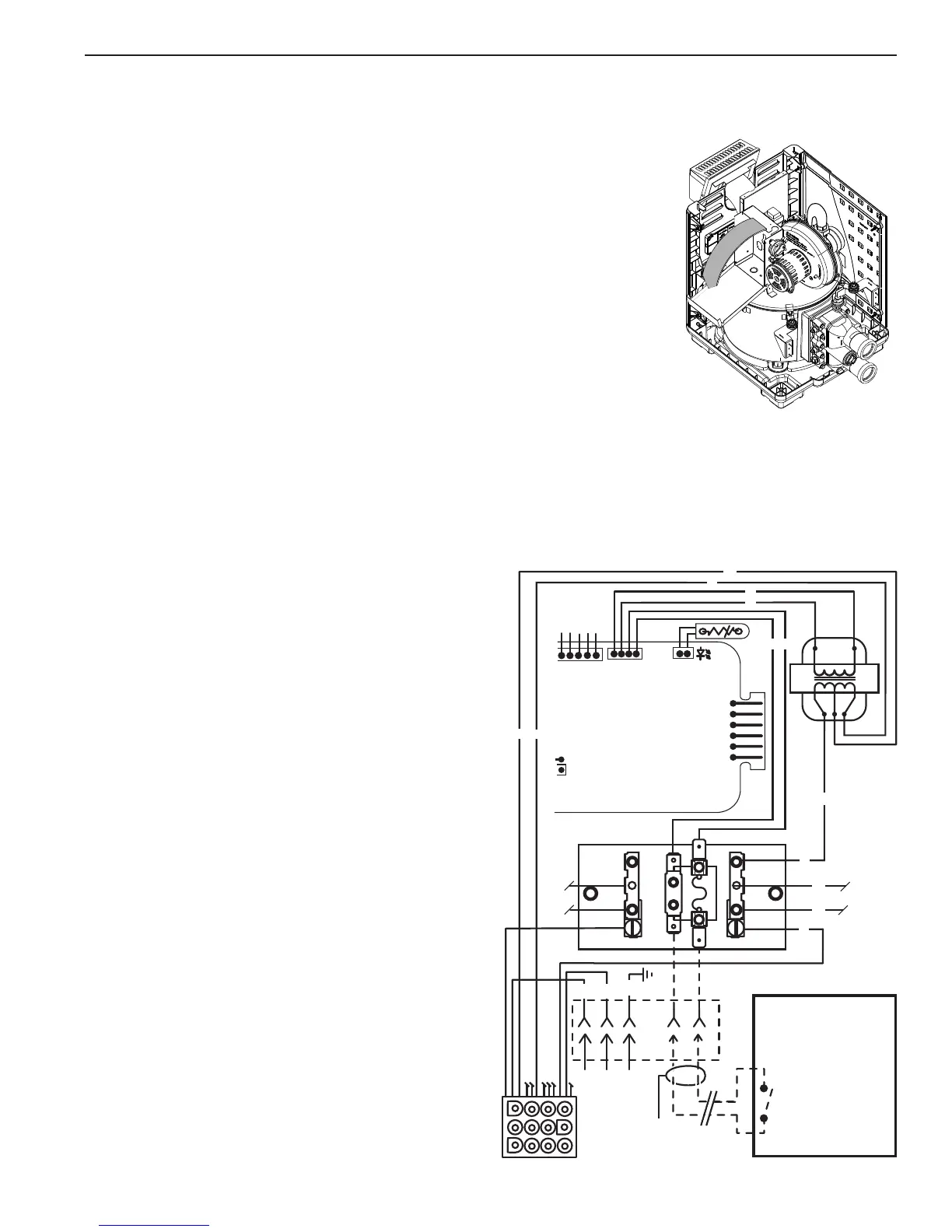
Figure 31.
REMOTE CONTROL CONNECTIONS
1. Switch off power to heater at main circuit breaker panel.
2. Unbolt and remove the access door panels.
3. Open control box cover (see Figure 31).
4a. T
o connect a 2-Wire Control (such as Pentair’s IntelliTouch
™
or EasyTouch
™
Control Systems) or a timer:
- Remove the factory installed jumper from the Fireman’s Switch terminals.
- Connect wires between the Fireman’s Switch terminals on the heater and the
relay. Connect wires from the controller or timer to the Fireman’s Switch.
Controller, timer or relay should be sized to handle 24VAC at 0.5 Amp (because
it will be completing the 24VAC control board circuit on the heater as shown in
Figure 32). DO NOT apply line voltage to the Fireman’s Switch terminals. Use
18 gauge wire with a minimum 1.2 mm (3/64 in.) thick insulation rated for a
temperature rise of at least 105° C.
-
Knock-outs are provided to route the wires through the bottom of the control box
and past the junction box.
4b. To connect a 3-Wire Control:
- Connect wires between the control board terminals on the heater and the external relays, as shown in Figure 33 on
page 26. Use at least 2 relays per heater, to allow for an “OFF setting” on each heater mode. Select relays that
can handle logic level switching. DO NOT apply line voltage to control board terminals.
-
Move jumper (as shown in Figure 33 on page 26) to enable external control and to disable the heater membrane pad’s
“Pool ON” and “Spa ON” buttons (the “OFF” key
on the membrane pad remains functional).
-
Knock-outs are provided to route the wires through
the bottom and the top of the control box and past
the junction box.
5. Close control box cover.
6. Re-install the access door panels.
To control heaters that are operated in parallel, connect wiring
at same locations on heater as 2-Wire or 3-Wire Control. It
is imperative that each control circuit is isolated from the
other control circuits, to avoid that current will flow from
one heater to another through the control circuits.
NOTICE: The fuse for the Fireman’s Switch is a 1.25 Amp
31.75 mm x 6.35 mm fast blow fuse, which is commonly
available.
GND
L1
GROUND (GND )
L2
JUNCTION
BOX
L1
L2
BM
FL
F1
L1
TRAN S
F
I
R
E
M
A
N
S
S
W
I
T
C
H
Fireman's Switch
Completes the heater
24 Volt AC Control
Board Circuit.
DO NOT connect this
circuit to Line Voltage!
YY
R
W
G/Y
Y
Y
TERMINAL BOARD
TRANS
TRANS
FUSE
FUSE
L2
Time Clock or Remote
(Purchase Separately –
Supplies Power to
Circulator Pump)
24VAC
24 VAC
BK
O
O
BK
W
R
BR
BL
W
12 Pin
Receptacle
VAL
TH
IND
GND
24VAC
24VAC
FS
THERMISTOR
OPERATING CONTROL
DISABLE TOGGLE
ENABLE TOGGL
E
MEMBRANE PAD
CONNECTION
9
1
J6
Figure 32.
Section 2. Installation