P/N 475106 Rev. A 2/2014 MASTERTEMP
™
Pool and Spa Heater Installation and User’s Guide
| 23
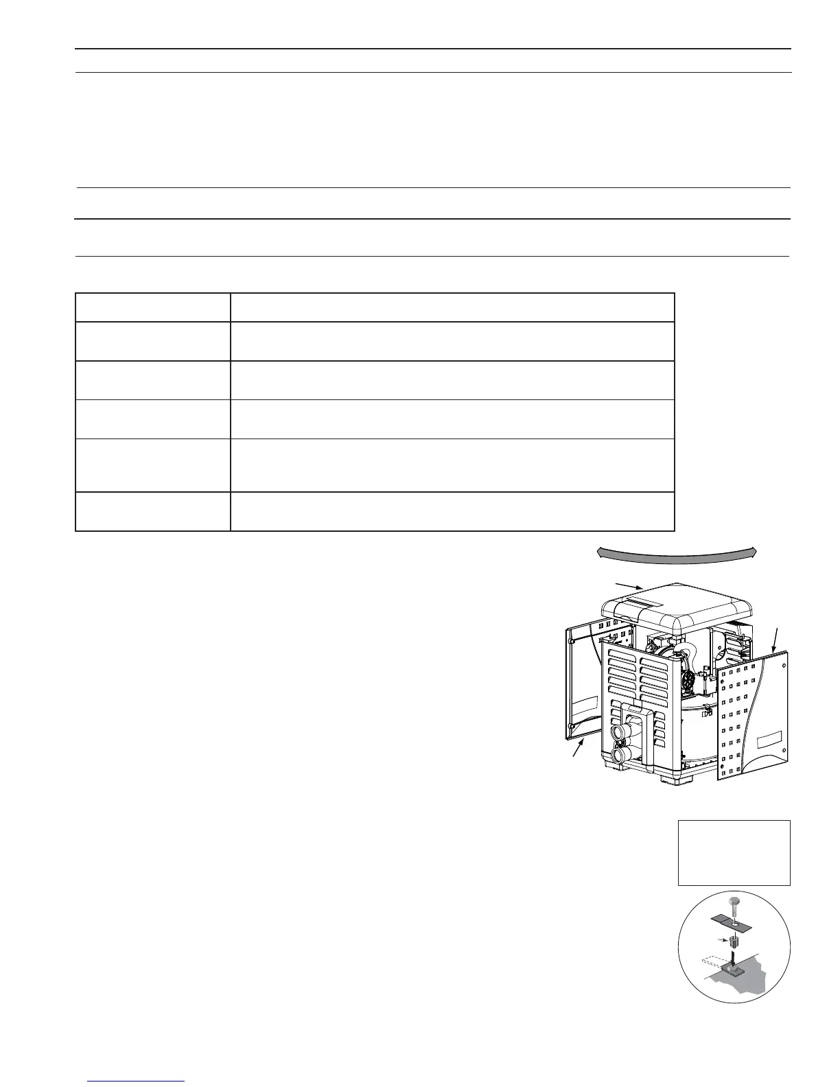
CONTROL PANEL INDEXING
On an outdoor shelter installation, the exhaust discharges into a vent pipe. Orient
the heater so that the vent pipe does not interfere with adjustment of the operating
controls. The control panel located on the top panel can be rotated to any of the
three sides of the heater for easy access, see Figure 28.
1. Remove the bolts from the door panels. Remove both door access panels.
2. Remove the four corner screws that secure the top panel. Lift the top
panel upward to remove the top panel.
3. Rotate the top panel to the desired position located at 90° angles. Note that
the control panel must NOT be located on the side where the vent is
located.
4. Replace the top panel down onto the side panels. Be sure that there are no
wires caught under the panel.
5. Secure the top panel using the four corner screws.
6. Reattach the door access panels.
FINAL INSTALLATION CHECK
After installation, the installer MUST test and check that the heater is operating and
functioning properly.
Some building codes require that the heater be anchored to the equipment pad or platform to
withstand high wind pressures created during hurricanes. A Bolt Down Bracket Kit, P/N 460738,
is available with anchor clamps designed to hold the unit to the equipment pad in high wind conditions,
see Figure 29. Installation of the anchor clamps are recommended in all installations.
Door
Acces
Panel
Top Panel
Door
Access Panel
Figure 28.
Lead
Anchor
For Heater mounting
bolts and clamps,
purchase separately
Bolt Down Bracket Kit,
Part No.
460738.
aerAstnanimatnoCylekiL
gnimmiwsdetanirolhC
sapsdnasloop
.dicacitairumrocirolhcordyhsahcus,sdicA.slacimehcgninaelcapsrolooP
dnanoitcurtsnocweN
saeragniledomer
dnatniapdna,sehsinrav,stniap,sevisehdanoitcurtsnoc,stnemecdnaseulG
.edirolhcmuidosromuiclacgniniatnocsrenaelcdnasexaW.sreppirtshsinrav
srolrapytuaeB
rosnobracorolhcgniniatnocsnaclosorea,sehcaelb,snoitulosevawtnenamreP
.snobracoroulf
rostnalpnoitaregirfeR
gnihsiniflairtsudnisuoirav
stnalpgnissecorpdna
.sevisehdanoitcurtsnoc,stnemecdnaseulg,sdica,stnaregirfeR
yrdnualdnagninaelcyrD
saera
srenaelcdnasexaW.enirolhcgniniatnocspaosyrdnualro,stnegreted,sehcaelB
.edirolhcmuidosromuiclac,enirolhcgniniatnoc
Corrosive Vapors and Possible Causes
Figure 29.
NOTE: KEEP A 150 CM (6 IN) MINIMUM CLEARANCE BETWEEN THE VENT PIPE AND
COMBUSTIBLE SURFACES. FOLLOW THE VENT MANUFACTURER’S INSTRUCTIONS
AND CODE REQUIREMENTS.
Each 90° bend reduces the maximum horizontal vent run by 3.6 m (12 feet) and each 45° bend in the vent run
reduces the maximum vent run by 1.8 m (6 feet). See Table 8 (page 22) for the maximum vent length using one
90° bend.
NOTE
After installation, installer must check for correct and safe operation of the heater.
Section 2. Installation