11
Rev. C 12-1-00 P/N 38033
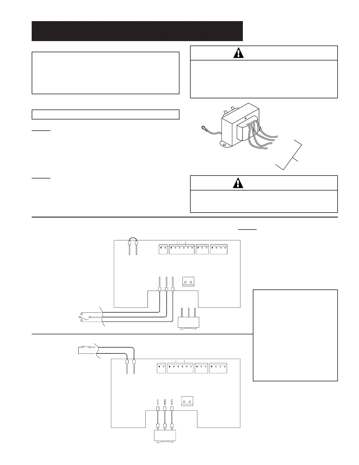
Transformer and Remote Wiring
Electrical - Rating
NOTE
If any of the original wiring supplied with the heater
must be replaced, the installer must supply No. 18
AWG 105° C., U.L. approved AWM low energy
stranded copper wire or it’s equivalent.
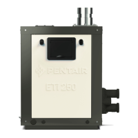
Transformer Wiring Instructions
The transformer is wired at the Factory for 240V.
CAUTION
The heater must be electrically grounded and
bonded in accordance with local codes or in ab-
sence of local codes, with the latest National
Electrical Codes ANSI/NFPA No. 70.
SPA
COM POOL
TPROBE
OUT RETURN
24 VAC
HILMT
IGNITION MOD
EXT SWITCH
THERMOSTAT CIRCUIT BOARD
POOL/
OFF/SPA
FRONT PANEL
THERMOSTAT SELECT SWITCH
TFUSE VALVE
REMOTE CONTROL
PRESS
SPA COM POOL TPROBE
OUT RETURN
24 VAC
HILMT
IGNITION MOD
EXT SWITCH
THERMOSTAT CIRCUIT BOARD
JUMPER REQUIRED IF NO 2 WIRE REMOTE SWITCH
POOL/
OFF/SPA
FRONT PANEL
THERMOSTAT SELECT SWITCH
TFUSE VALVE
REMOTE POOL/OFF/SPA
THERMOSTAT SELECT SWITCH
PRESS
NOTE: When connecting
a remote control to the
MiniMax wiring, you must
install the low voltage
remote wires in separate
conduit from ANY line
voltage wires. Failure to
follow these instructions
will cause the thermostat
relay to react erratically.
Remote Switch Dual Therm IID Only
3 Wire Remote
2 Wire Remote
Supply voltage
Connect to
these wires
RED
W/with RED
W/with BLACK
BLACK
240V
-
The red tracer and the black tracer wires are
wired together. (Do not connect the tracer wires to
any power.) Connect one power supply wire to the
solid red wire and the other power supply wire to the
solid black wire.
120V
-
To wire the transformer for 120V, twist the
red and the red tracer wires together and twist the
black and the black tracer wires together. Connect
the 120V power supply wires to these wires, one to
the red/red tracer, and one to the black/black tracer.
WARNING
If the transformer is wired for the wrong voltage
supply, the transformer will fail.
 Loading...