15
PN957 (25-06-20)
CABLE INSTALLATION
Three 1/2” conduit knockouts are provided on the bottom of the
Pentair Pentek Intellidrive
®
Constant Pressure Pump Controller
enclosure for the I/O wires.
Break out the closest 1/2” knockout and route the wires through.
Use a cord grip to prevent the wire from rubbing and causing a
short.
NOTE: Never run low voltage I/O wire through the same conduit hole
as the 230V input wires or motor wires.
To connect the external wires to the terminals:
1. Strip wire ½ inch
2. Push spring terminal up with finger or slotted screwIntellidriver
3. Insert wires from bottom
4. Release spring terminal
CONNECTION EXAMPLES
Figures 15-18 show various connection schemes for typical
applications. Table 6 describes each I/O terminal, including purpose
and rating.
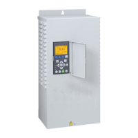
I/O CONNECTIONS
Figure 15 - Input with Internal 24 Volt Supply
115 VAC
or
230 VAC
+
-
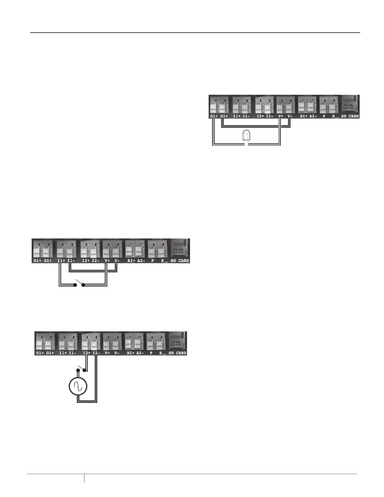
Figure 16 - External Input with ExternalSupply
Figure 17 - Output Relay with Internal24 Volt Supply
 Loading...