7
Step 4. Ground the pump permanently using a wire of
the same size as that specified in wiring chart,
below. Make ground connection to green
grounding terminal under motor canopy marked
GRD. or .
Step 5. Connect ground wire to a grounded lead in the
service panel or to a metal underground water
pipe or well casing at least 10 feet long. Do not
connect to plastic pipe or insulated fittings.
Step 6. Protect current carrying and grounding conduc-
tors from cuts, grease, heat, oil, and chemicals.
Step 7. Connect current carrying conductors to ter-
minals L1 and L2 under motor canopy. When
replacing motor, check wiring diagram on motor
nameplate against Figure 3. If the motor wir-
ing diagram does not match either diagram in
Figure 3, follow the diagram on the motor.
IMPORTANT: 115/230 Volt single phase models are
shipped from factory with motor wired for 230 volts. If
power supply is 115 volts, remove motor canopy and
reconnect motor as shown in Figure 3. Do not try to run
motor as received on 115 volt current.
Step 8. Motor has automatic internal thermal overload
protection. If motor has stopped for unknown
reasons, thermal overload may restart it unex-
pectedly, which could cause injury or property
damage. Disconnect power before servicing
motor.
Step 9. For more assistance on this procedure or the
wiring diagrams, consult a licensed electrician.
Distance in Feet (M) from Meter to Motor for AWG Wire Sizes
HP Wire Volts #14 AWG #12 AWG #10 AWG #8 AWG #6 AWG #4 AWG #2 AWG #0 AWG
1
1
115 40 — 51’ (16) 82’ (25) 128’ (39) 182’ (55) 296’ (90) 432’ (132) 592’ (180)
230 20 134’ (41) 204 (62) 326 (99) 511 (156) 770 (235) 1183 (361) — —
3
230 10 276 (84) 437 (133) 685 (209) 1055 (322) — — — —
460 5 1103 (336) — — — — — — —
1-1/2
1
115 45 — — 64 (20) 100 (30) 151 (46) 232 (271) 338 (103) 463 (141)
230 25 105 (32) 160 (49) 255 (78) 400 (122) 602 (183) 926 (282) 1351 (412)
3
230 15 197 (60) 312 (95) 489 (149) 753 (230) 1785 (544) — — —
460 7 - 1/2 788 (240) 1249 (381) — — — — — —
2
1 230 30 85 (26) 129 (39) 206 (63) 323 (98) 486 (148) 747 (228) 1090 (332) —
3
230 20 167 (51) 265 (81) 415 (126) 640 (195) 982 (299) 1515 (462) — —
460 10 669 (204) 1060 (323) — — — — — —
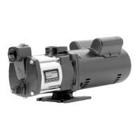
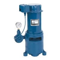
ELECTRICAL
Fuse
Rating
(amps)
Discharge Depth To Water In Feet (Meters)
Pressure
Catalog No. Order No. HP in PSI (kPa) 5’ (1.5) 10’ (3) 15’ (4.6) 20’ (6.1) 25’ (7.6)
DMC-2-100
07052
1
20 (138) 43 (163) 42 (159) 41 (155) 39 (148) 37 (140)
30 (207) 36 (136) 35 (132) 33 (125) 31 (117) 28 (106)
40 (276) 27 (102) 26 (98) 23 (87) 19 (72) 16 (61)
50 (345) 14 (53) — — — —
DMC-2-150 07053
1-1/2
20 (138) 49 (185) 47 (178) 46 (174) 45 (170) 44 (167)
30 (207) 43 (163) 42 (159) 41 (155) 40 (151) 39 (148)
40 (276) 37 (140) 36 (136) 35 (132) 33 (125) 31 (117)
50 (345) 30 (114) 27 (102) 25 (95) 22 (83) 19 (72)
60 (413) 15 (57) 10 (38) — — —
DMC-2-200
07054
2
30 (207) 49 (185) 48 (182) 47 (178) 46 (174) 46 (174)
and 40 (276) 44 (167) 43 (163) 42 (159) 40 (151) 39 (148)
DMC-2-200-3 50 (345) 38 (144) 36 (136) 35 (132) 33 (125) 31 (117)
(3-phase) 60 (413) 30 (114) 27 (102) 24 (91) 21 (79) 15 (57)
Pumping Capacity in GPM (LPM) at Indicated Pressure and Depth
Recommended Wire and Fuse Sizes
 Loading...