Installation 4
BEFORE YOU INSTALL YOUR PUMP
NOTICE: Well must not be more than 20’ depth to water.
1. Long runs and many fittings increase friction and reduce flow. Locate
pump as close to well as possible: use as few elbows and fittings as
possible.
2. Be sure well is clear of sand. Sand will plug the pump and void the
warranty.
3. Protect pump and all piping from freezing. Freezing will split pipe,
damage pump and void the warranty. Check locally for frost protection
requirements (usually pipe must be 12” below frost line and pump must
be insulated).
4. Be sure all pipes and foot valve are clean and in good shape.
5. No air pockets in suction pipe.
6. No leaks in suction pipe. Use PTFE pipe thread sealant tape to seal pipe
joints.
7. Unions installed near pump and well will aid in servicing. Leave room
use wrenches.
8. Pump body may explode if used as a booster pump.
DO NOT use in a booster appli cation.
WELL PIPE INSTALLATION
NOTICE: Use the installation method below which matches your well type.
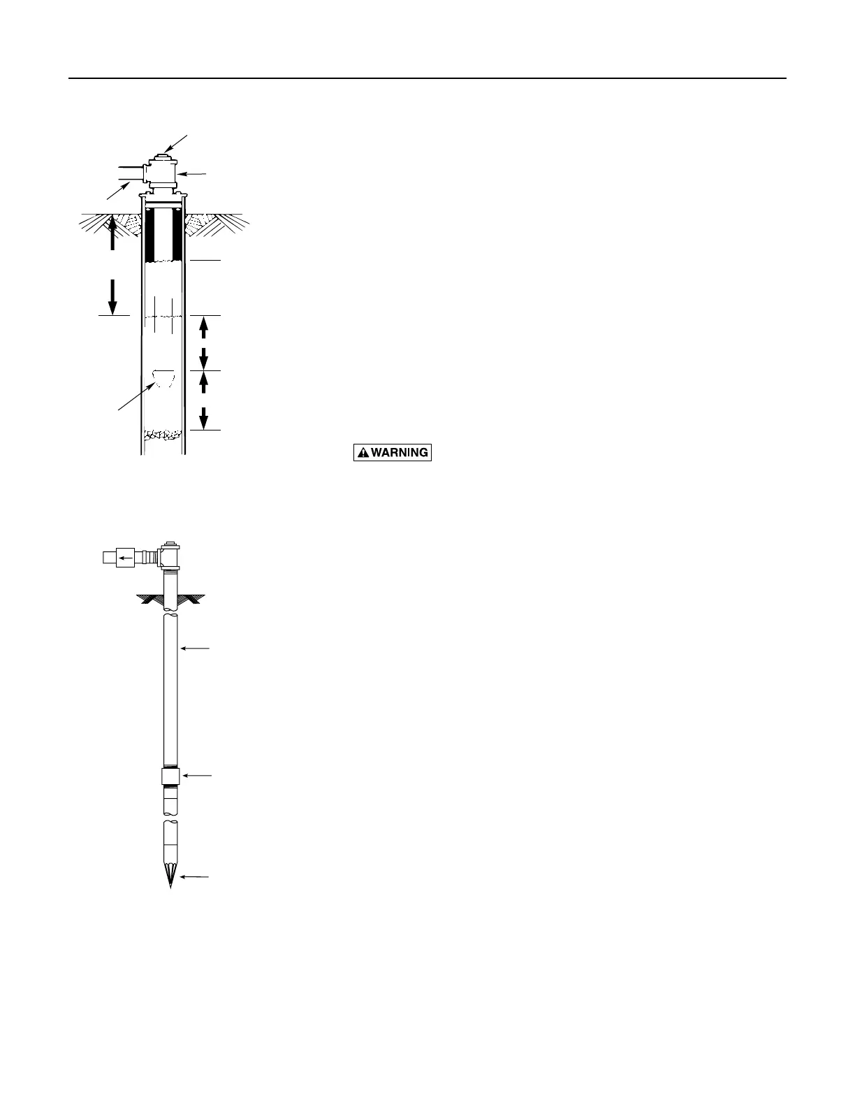
CASED WELL INSTALLATION
1. Inspect foot valve to be sure it works freely. Inspect strainer to be sure it
is clean.
2. Connect foot valve and strainer to the first length of suction pipe and
lower pipe into well. Add sections of pipe as needed, using PTFE pipe
thread sealant tape on male threads. Be sure that all suction pipe is
leakproof or pump will lose prime and fail to pump. Install foot valve
10 to 20 feet below the lowest level to which water will drop while
pump is operating (pumping water level). Your well driller can furnish
this in formation.
3. To prevent sand and sediment from entering the pumping system, the
foot valve/strainer should be at least 5 feet above the bottom of the
well.
4. When the proper depth is reached, install a sanitary well seal over the
pipe and in the well casing. Tighten the bolts to seal the casing.
5. When using a foot valve, a priming tee and plug as shown in Figure 1
are recommended.
DUG WELL INSTALLATION
Same as cased well installation.
DRIVEN POINT INSTALLATION
1. Connect the suction pipe to the drive point as illustrated in Figure 2.
Keep horizontal pipe run as short as possible. Use PTFE pip thread
sealant tape on male pipe threads. Multiple well points may be
necessary to provide sufficient water to pump.
2. Install a check valve in horizontal pipe. Flow arrow on check valve
must point toward pump.
Suction
pipe
Foot
Valve
Priming plug
Priming tee
Standing water
level (pump off)
Drawdown water
level (pump on)
10-20' (3-6 m)
20' (6 m) max.
At least 5 feet (1.5 m)
828 0993
Check valve
Steel drive pipe
Drive coupling
Driven point
Figure 1: Cased/Dug Well Installation
Figure 2: Driven Point Installation

 Loading...