Electrical / Operation 7
2. Provide a correctly fused disconnect switch for protection while work-
ing on motor. Consult local or national electrical codes for switch
requirements.
3. Disconnect power before servicing motor or pump. If the disconnect
switch is out of sight of pump, lock it open and tag it to prevent unex-
pected power application.
4. Ground the pump permanently using a wire of the same size as that
specified in wiring chart, below. Make ground connection to green
grounding terminal under motor canopy marked GRD. or .
5. Connect ground wire to a grounded lead in the service panel or to a
metal underground water pipe or well casing at least 10 feet long. Do
not connect to plastic pipe or insulated fittings.
6. Protect current carrying and grounding conductors from cuts, grease,
heat, oil, and chemicals.
7. Connect current carrying conductors to terminals L
1
and L
2
under
motor canopy. When replacing motor, check wiring diagram on motor
nameplate against Figure 6. If the motor wiring diagram does not match
either diagram in Figure 6, follow the diagram on the motor.
IMPORTANT: 115/230 Volt single phase models are shipped from factory
with motor wired for 230 volts. If power supply is 115 volts, remove motor
canopy and reconnect motor as shown in Figure 6. Do not try to run motor
as received on 115 volt current.
8. Motor has automatic internal thermal overload protection. If motor has
stopped for unknown reasons, thermal overload may restart it unexpect-
edly, which could cause injury or property damage. Disconnect power
before servicing motor.
9. If this procedure or the wiring diagrams are confusing, consult a
licensed electrician.
PRIMING THE PUMP
NOTICE: ‘Priming’ refers to the pump expelling all air in the system and begin-
ning to move water from its source out into the system. It does not refer only to
pouring water into the pump (although pouring water in is usually the first step).
NOTICE: NEVER run pump dry. Running pump with out water in it will
damage seals and can melt impeller and diffuser. To prevent damage, fill
pump with water before starting.
1. Remove priming plug (Figure 9).
2. Make sure suction and discharge valves and any hoses on discharge
side of pump are open.
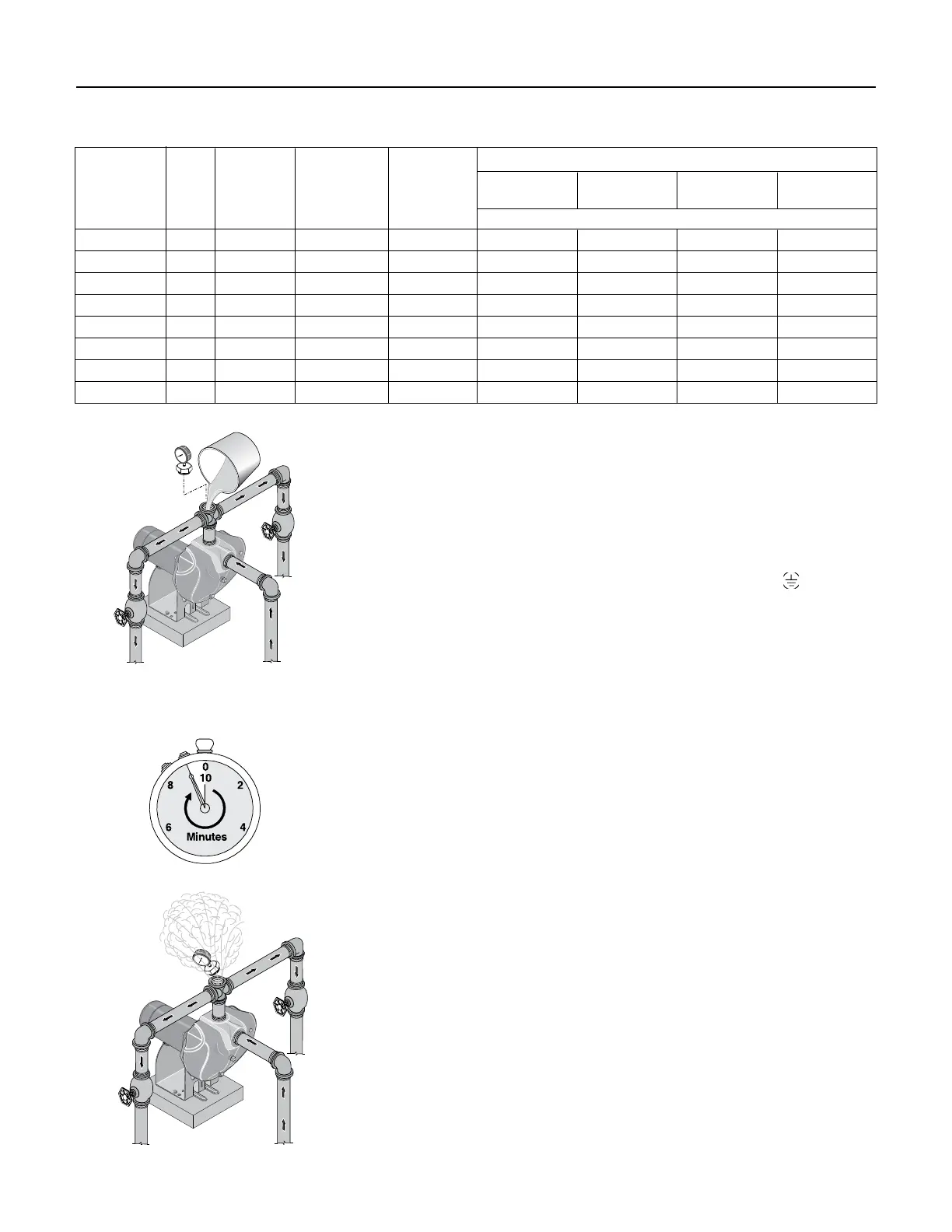
Wiring Chart – Recommended Wire and Fuse Sizes
DISTANCE IN FEET(METERS) FROM MOTOR TO SUPPLY
0 - 50 51 - 100 101 - 200 201 - 300
Max. Load Volts/Hz Branch Fuse
(0 - 15) (31 - 61) (62 - 91) (92 - 122)
Model HP Amp Phase Rating Amp AWG WIRE SIZE (mm
2
)
DS3HE-01 1 14.8/7.4 115/230/60/1 20/15 12/14 (3/2) 12/14 (3/2) 8/14 (8.4/2) 6/14 (14/2)
DS3HE3-01 1 3.6/1.8 230/460/60/3 15/15 14/14 (2/2) 14/14 (2/2) 14/14 (2/2) 14/14 (2/2)
DS3HF-01 1-1/2 20/10 115/230/60/1 25/15 10/14 (5.5/2) 10/14 (5.5/2) 8/14 (8.4/2) 6/12 (14/3)
DS3HF3-01 1-1/2 4.7/2.35 230/460/60/3 15/15 14/14 (2/2) 14/14 (2/2) 14/14 (2/2) 14/14 (2/2)
DS3HG-01 2 24/12 115/230/60/1 30/15 12/14 (3/2) 10/14 (5.5/2) 6/14 (14/2) 6/12 (14/3)
DS3HG3-01 2 5.8/2.9 230/460/60/3 15/15 14/14 (2/2) 14/14 (2/2) 14/14 (2/2) 14/14 (2/2)
DS3HHG-01 2-1/2 26/12 115/230/60/1 35/15 12/14 (3/2) 10/14 (5.5/2) 6/14 (14/2) 6/8 (14/8.4)
DS3HHG3-01 2-1/2 6.9/3.45 230/460/60/3 15/15 14/14 (2/2) 14/14 (2/2) 14/14 (2/2) 14/14 (2/2)
Figure 9: Remove Priming Plug and Fill
Pump Before Starting
Figure 10: Run Ten Minutes or Less
Figure 11: Do Not Run Pump with
Discharge Shut-off
20
100
80
60
40
20
100
80
60
40

 Loading...