HMSC pumps come equipped with pressure switch set
to operate within a 20-40 PSI range. HMSD, HMSE, and
HMSF pumps have 30-50 PSI pressure switches. When
pump is used with precharged tank in system, set tank
pre-charge at 18 PSI with a 20-40 PSI switch; set tank pre-
charge at 28 PSI with a 30-50 PSI switch. Check tank pre-
charge annually with an ordinary tire gauge. Pre-charge is
set with no water pressure on system.
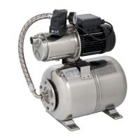
Priming the Shallow Well Pump
Never run pump dry. Running pump without
water may cause pump to overheat, damaging seal and pos-
sibly causing burns to persons handling pump. Fill pump with
water before starting.
Never run pump against closed discharge.
To do so can boil water inside pump, causing hazardous
pressure in unit, risk of explosion and possibly scalding per-
sons handling pump.
To prime the pump, completely open the priming valve locat-
ed just below the suction opening on the tank body by turning
the valve stem counter-clockwise all the way until it stops.
This valve may be left open during operation as a shallow
well pump with no jet. See Figure 3 and “NOTICE” below.
Remove priming plug from top of elbow (see Figure 3), and
fill with clean water. Replace plug.
Start pump and between 45-60 seconds. If water is not being
pumped, turn off pump and repeat priming process.
NOTICE: If a bolt-on jet is being used, after pump is primed,
close the priming valve during operation as a shallow well
pump.
Service – Draining for Winter
Do not touch an operating motor. Modern
motors are designed to operate at high temperatures. To
avoid burns when servicing pump, allow it to cool for 20 min-
utes after shut-down before handling.
When the pump is to be disconnected from service, or is in
danger of freezing, it should be drained. The pump has a
drain plug which must be removed. Remove the priming plug
to vent the pump.
If pump and motor are damaged due to freezing, the
Warranty is void.
3
To Service
Priming
Valve
From
Well
1" Pipe Plug
Plastic Pipe
Adapter
Hose Clamp
Plastic
Hose
Pipe fittings not furnished
Priming Plug &
1/2" Street Elbow
240 1093
Figure 3 – Shallow Well Installation
TABLE I
Recommended Fusing and Wiring Data – 60 Cycle Motors
DISTANCE IN FEET FROM MOTOR TO METER
BRANCH 0’ 101’ 201’ 301’ 401’
MAX. FUSE* to to to to to
MOTOR LOAD RATING 100’ 200’ 300’ 400’ 500’
HP VOLTS AMPERES AMPS
WIRE SIZE
3/4 115 14.8 20 12 8 6 6 4
3/4 230 7.4 15 14 14 14 12 10
1 115 19.2 25 10 8 6 4 4
1 230 9.6 15 14 14 12 10 10
1-1/2 115 24.0 30 10 6 6 4 3
1-1/2 230 12.0 15 14 14 12 10 10
*Fusetrons are recommended instead of fuses on all motor circuits.
 Loading...