IDENT-I • IVI-KHA6-4HRX, IVI-KHD2-4HRX
Operating control interface units using the 3964R protocol
Subject to reasonable modifications due to technical advances. Copyright Pepperl+Fuchs, Printed in Germany
epperl+Fuchs Group • Tel.: Germany (06 21) 7 76-0 • USA (330) 4 25 35 55 • Singapore 7 79 90 91 • Internet http://www.pepperl-fuchs.com
Date of issue 27.08.2001
35
8 Operating control interface units using the 3964R protocol
8.1 Notes on the 3964R protocol
The 3964R procedure was defined to allow the transfer of data via a serial point-to-
point connection in which the majority of data errors and time-outs are detected and
corrected by the protocol. The 3964R protocol is an asynchronous bit-serial transmis-
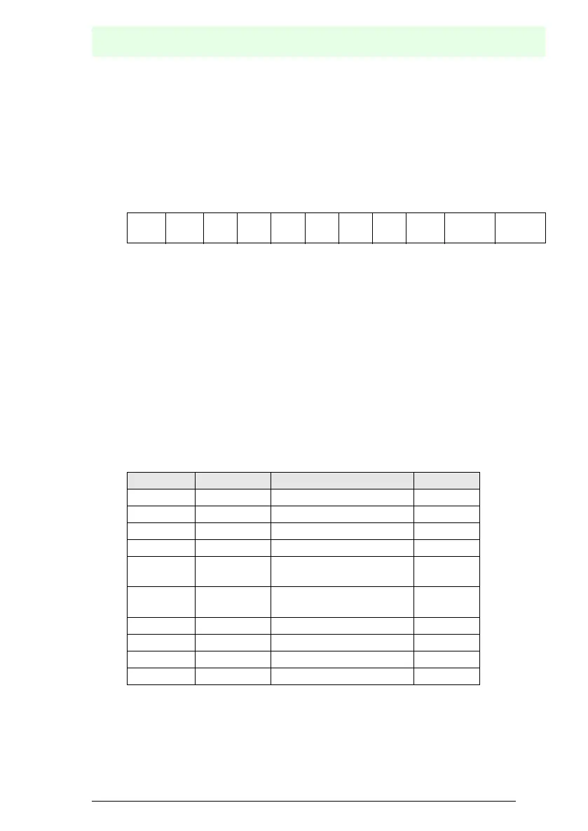
sion procedure. A character frame consists of one start bit, 8 data bits, one even parity
bit and one stop bit.
Bild 8.1: 11-bit character frame
The transmission rate is set via DIP switches S1, S2, and S3.
Communication always starts with a command message either to transmit data
(SEND messages) or to fetch data (FETCH messages).
The control interface unit replies with a "Response" message, with or without data.
A SEND message comprises a message header and data. A FETCH message com-
prises a message header only.
The message header consists of 10 bytes of information about the data target in the
case of a SEND message, or information on the data source, in the case of a FETCH
message.
If the RK 512 Interpreter is used, the message header is structured as follows:
Bild 8.2: Message header
Start
bit
0
LSB
123456 7
MSB
Even
parity
Stop
bit
Byte Code Description Check
1 00h Message yes
2 00h Identifier yes
3 ’E’ Message "input" yes
4 x Type of data no
5 xx Target address of data
(high)
no
6 xx Target address of data
(low)
no
7 yy Volume of data (high) no
8 yy Volume of data (low) no
9 FFh Coordination marker no
10 FFh Coordination marker no
 Loading...


