AS-Interface
Appendix: AS-i Slave Lists and Data Telegrams
Subject to reasonable modifications due to technical advances. Copyright Pepperl+Fuchs, Printed in Germany
Pepperl+Fuchs Group · Tel.: Germany (621) 776-0 · USA (330) 4253555 · Singapore 7799091 · Internet http://www.pepperl-fuchs.com
issue date 12.10.1999
52
11.3 Structure of the Profibus-DP Data Telegram
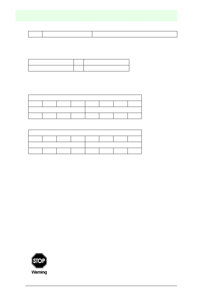
11.3.1 Structure of the AS-i data window
with K = number of AS-i slaves + 1 (the AS-i flags are always additionally transmitted)
N = K/2
Bit allocation by slave 3 and slave 2 in byte 1
Bit allocation by slave (K-1) and slave (K-2) in byte (N-1)
The following AS-i Master flags are transmitted in the I/O field of the DP data telegram
in place of the input data of slave 0:
Bit 0 (Config_OK):
0 = configuration OK
1 = configuration error
Bit 1 (APF, AS-i power fail):
0 = power supply on AS-i sufficient
1 = power supply on AS-i insufficient
Bit 2 (Normal_operation_active):
0 = normal operation active
1 = normal operation not active
Bit 3 (Configuration_active):
0 = protected mode
1 = configuration mode
The following AS-i Master flags are transmitted in the I/O-field of the DP data telegram
in place of the output data of slave 0:
Bit 7: Offline_Ready off-line mode active
byte 0 ... byte N-1
slave 1 AS-i flags ... slave(K-1) slave(K-2)
byte 1
bit 7 bit 6 bit 5 bit 4 bit 3 bit 2 bit 1 bit 0
slave 3 slave 2
D3 D2 D1 D0 D3 D2 D1 D0
byte (N-1)
bit 7 bit 6 bit 5 bit 4 bit 3 bit 2 bit 1 bit 0
slave (K-1) slave (K-2))
D3 D2 D1 D0 D3 D2 D1 D0
If the AS-i flags shall not be used you have to make sure that these four
bits in the I/O-field are set to zero!
 Loading...