Clarus 600/680 GC User’s Guide
2-5
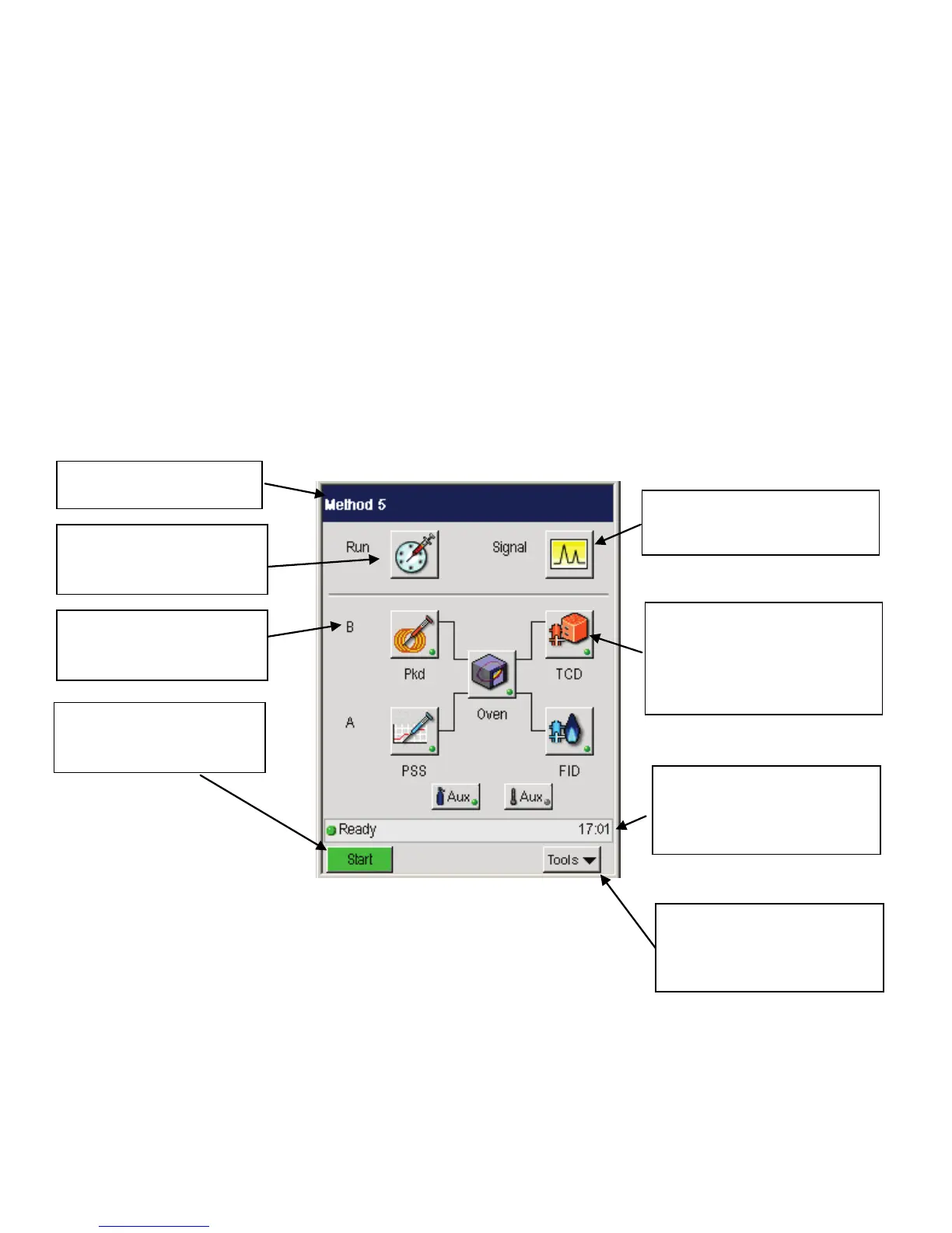
The following Status Screen shows the different sections of the user interface.
The Status Screen displays icons that provide quick access to major areas of the
system. The injector and detector buttons show graphic representations of the
devices for each channel. If a heated auxiliary zone is configured, the Aux button
with a thermometer appears active on the bottom of the screen. The Aux zone
button with the carrier gas icon indicates that the PPC carrier gas zone is active.
The icon buttons that represent the heated zones (injectors, detectors, oven, and
Aux if configured) include a light to indicate the ready/not ready status. A red
blinking light indicates not ready and a steady green light indicates ready status.
Click here to view the Signal. If
a method is not running the
screen will display a baseline.
The Title bar displays the
name of the active method.
access to the Autosampler
and Manual Inject settings.
Channel A to emulate the
order on top of the GC.
The Icon buttons provide quick
access to all configured areas of
the instrument. An indicator
light shows the ready/not ready
status of each heated zone.
The status bar displays the
overall ready/not ready status
as well as text messages and
the real time clock/date
The bottom bar displays the
Tools pop up menu. When the
system is running the Stop
button also appears.
The Start button appears so
you can start or stop a run.
 Loading...